
A thermally-driven ejector refrigeration cycle can turn 100 kW of low-grade waste heat into roughly 19 kW of usable cooling — no compressor, no electricity input for the "compression" step. Here's the fluid selection, the mass-flow and pressure numbers, the physical size of the hardware, and a machinable, flat-plate ejector design.
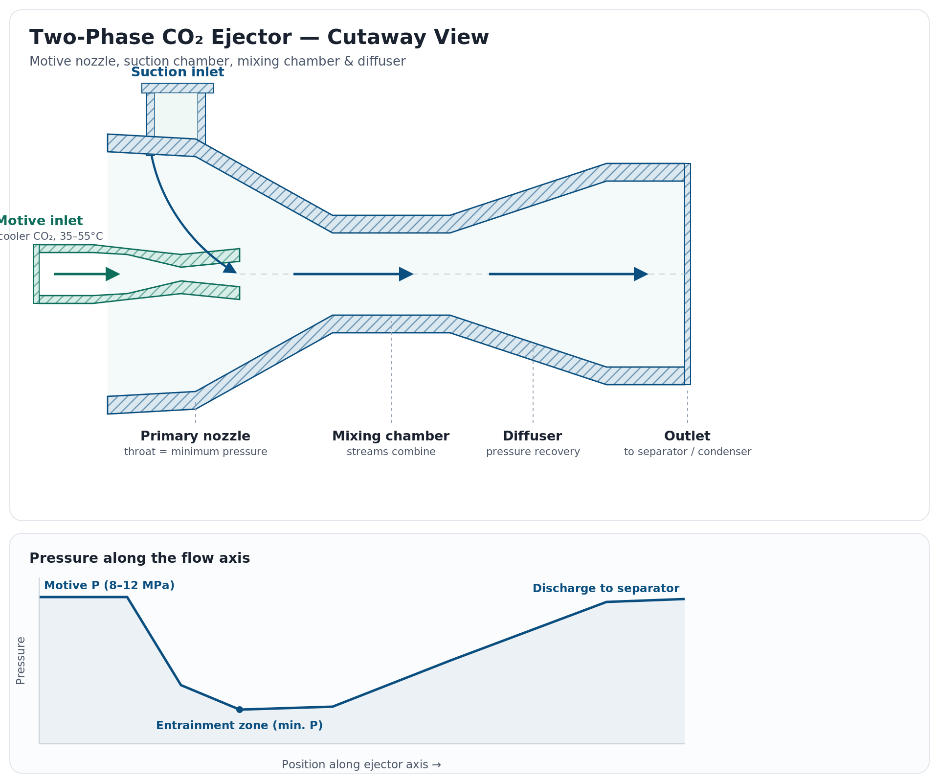
Ejector refrigeration uses waste heat, not shaft work, to move a refrigerant from evaporator pressure up to condenser pressure. A generator (boiler) uses the waste heat to vaporize a working fluid at high pressure; that vapor accelerates through a supersonic nozzle inside the ejector, and the resulting low-pressure jet entrains a second stream of vapor from the evaporator — the stream that actually produces the cooling effect. The two streams mix, then recompress in a diffuser and condense together. No compressor, no moving parts.
The obvious first question for a data-center application is which fluid to use. We compared R245fa against CO₂ and the answer is one-sided: CO₂'s critical point is 31.0 °C / 73.8 bar, meaning CO₂ cannot be boiled above 31 °C at any pressure. A classic heat-driven generator simply cannot function with CO₂ at any realistic data-center waste-heat temperature. We even modeled the best-case workaround — supercritical CO₂ heated to 90 °C at 90 bar, expanded through the ejector, then diffuser-recompressed back toward gas-cooler pressure — and found that even with zero secondary entrainment (i.e. producing no cooling at all), the diffuser only recovers to about 76.5 bar, short of the 90 bar needed just to close the loop. Real CO₂ ejector systems (e.g. supermarket R744 racks) always pair the ejector with a mechanical compressor — that's a fundamentally different, electrically-driven architecture, not a waste-heat-only cycle. R245fa is the correct fluid for a purely thermally-driven design in this temperature range.
| Temperature | 90.0 °C194.0 °F |
| Pressure | 10.06 bar145.9 psia |
| Mass flow | 447 g/s1,609 kg/h · 3,548 lb/h |
| Temperature | 10.0 °C50.0 °F |
| Pressure | 0.824 bar12.0 psia |
| Mass flow | 113 g/s407 kg/h · 898 lb/h |
| Temperature | 35.0 °C95.0 °F |
| Pressure | 2.12 bar30.7 psia |
| Mass flow | 560 g/s2,017 kg/h · 4,446 lb/h |
Model basis: 1-D nozzle/mixing/diffuser gas-dynamics with nozzle efficiency 0.90, mixing efficiency 0.90, diffuser efficiency 0.85. Entrainment ratio ω = ṁsecondary/ṁprimary = 0.253, solved so the diffuser exactly recompresses the mixed stream to condenser pressure (critical/double-choked design point). Results (ω ≈ 0.2–0.5, COP ≈ 0.15–0.35) fall within the range reported in published R245fa ejector-refrigeration studies at similar generator/condenser/evaporator temperatures.
| Stream | Role | Temperature | Pressure | Mass flow |
|---|---|---|---|---|
| Generator inlet | Motive (primary) | 90.0 °C / 194.0 °F | 10.06 bar / 145.9 psia | 447 g/s · 1,609 kg/h · 3,548 lb/h |
| Evaporator inlet | Suction (secondary) | 10.0 °C / 50.0 °F | 0.824 bar / 12.0 psia | 113 g/s · 407 kg/h · 898 lb/h |
| Condenser inlet | Mixed discharge | 35.0 °C / 95.0 °F | 2.12 bar / 30.7 psia | 560 g/s · 2,017 kg/h · 4,446 lb/h |
Sizing the throat, nozzle, mixing throat and diffuser from the mass flows above (choked-flow gas dynamics with real R245fa properties) gives a device on the order of half a meter long, with a throat only about a centimeter across (which can be mounted horizontally or vertically):
| Feature | Metric | Imperial |
|---|---|---|
| Throat (w × h) | 10.1 × 10.0 mm | 0.40 × 0.39 in | All Item Dimensions available through licensing |
| Plate stock (L × W × t) | 530 × 112 × 18 mm | 20.8 × 4.4 × 0.71 in |
A hybrid construction is the practical answer. The supersonic motive nozzle, throat, and mixing section are small and precision-critical — shock-free supersonic expansion is sensitive to wall shape — but at this scale they can be milled directly as a tapered “V” groove into an aluminum plate, sealed with a bolted, O-ring-gasketed cover plate. This planar/slot ejector approach is used in research prototypes and costs a fraction of what axisymmetric (lathe-turned) hardware costs, at a penalty of roughly 10–15% lower entrainment efficiency from corner losses in the rectangular channel versus a true round bore.
The diffuser is a different story: it's subsonic, far less shape-sensitive, and its exit is large (ø74 mm). Carried flat at a 10 mm groove depth, that exit would need to be over 500 mm wide — not practical. So the design bores the diffuser out into a round boss, onto which a standard pipe stub is brazed or welded for the condenser line. If maximum efficiency matters more than machining cost, a fully axisymmetric, lathe-turned ejector remains the industry-standard choice.
Mechanical layout: plan view of the milled aluminum base plate, section A–A through the mixing throat, and the full dimension table in metric and imperial units. This layout is available for licensing.
The ejector's 0.19 COP is a thermal ratio (cooling out ÷ heat in) and isn't directly comparable to a heat pump's COP, which is electrical (cooling out ÷ electricity in). A fair comparison benchmarks a standard vapor-compression chiller running between the same 10 °C evaporator and 35 °C condenser, then compares actual electricity cost.
Carnot's ideal limit for that lift is COP 11.3. Modeling a real single-stage cycle (R134a, 75% isentropic compressor efficiency) gives COP ≈ 7.4 — a best-case, high-efficiency number. Typical data-center-industry hardware runs lower once real heat exchangers, motor losses, and auxiliaries are included: water-cooled chillers commonly land around COP 5–6 (0.6–0.7 kW/ton), air-cooled chillers around COP 3–3.5 (1.0–1.2 kW/ton). The ejector, by contrast, has no compressor — its only electrical load is the small liquid feed pump moving condensate back up to generator pressure (ΔP ≈ 7.9 bar), which works out to about 0.39 kWe regardless of how much cooling it produces. Against its 18.9 kW output that's an electrical COP of roughly 49, because the primary energy is waste heat that's otherwise being thrown away.
The ejector can't be sized to replace the plant's primary chiller — its 0.19 thermal COP means it takes 100 kWth of waste heat to make only 18.9 kWth of cooling. For context, here's what a standard electric chiller would cost to carry that entire 100 kW load on its own:
| Chiller type | COP | Electric power | $/hr | $/yr (8,760 hr) |
|---|---|---|---|---|
| Ideal single-stage model | 7.4 | 13.5 kWe | $2.71 | $23,705 |
| Water-cooled (typical) | 5.5 | 18.2 kWe | $3.64 | $31,855 |
| Air-cooled (typical) | 3.5 | 28.6 kWe | $5.71 | $50,057 |
Bottom line: the ejector isn't a chiller replacement, it's a waste-heat-to-cooling converter that runs on pennies of pump electricity. Deployed as a bolt-on ahead of the primary chiller, it captures heat that's already being rejected and turns it into roughly 18.9 kW of supplemental cooling, offloading that much work — and about $4,000–$9,000/yr of electricity — from the site's standard chiller plant, for its own running cost of under $700/yr.
|
| CONTACT Email: greg@infinityturbine.com | AMP | PDF |