PDF Publication Title:
Text from PDF Page: 003
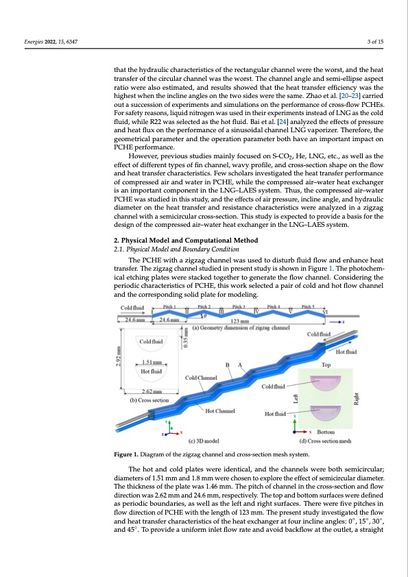
Energies 2022, 15, 6347 3 of 15 rectangular channel were the worst, and the heat transfer of the circular channel was Energies 2022, 15, x FOR PEER REVIEW 3 that the hydraulic characteristics of the rectangular channel were the worst, and the heat worst. The channel angle and semi-ellipse aspect ratio were also estimated, and re transfer of the circular channel was the worst. The channel angle and semi-ellipse aspect showed that the heat transfer efficiency was the highest when the incline angles on ratio were also estimated, and results showed that the heat transfer efficiency was the two sides were the same. Zhao et al. [20–23] carried out a succession of experiments highest when the incline angles on the two sides were the same. Zhao et al. [20–23] carried simulations on the performance of cross-flow PCHEs. For safety reasons, liquid nitr out a succession of experiments and simulations on the performance of cross-flow PCHEs. was used in their experiments instead of LNG as the cold fluid, while R22 was selecte For safety reasons, liquid nitrogen was used in their experiments instead of LNG as the cold the hot fluid. Bai et al. [24] analyzed the effects of pressure and heat flux on the pe fluid, while R22 was selected as the hot fluid. Bai et al. [24] analyzed the effects of pressure mance of a sinusoidal channel LNG vaporizer. Therefore, the geometrical parameter and heat flux on the performance of a sinusoidal channel LNG vaporizer. Therefore, the the operation parameter both have an important impact on PCHE performance. geometrical parameter and the operation parameter both have an important impact on PCHE performance. However, previous studies mainly focused on S-CO2, He, LNG, etc., as well as effect of different types of fin channel, wavy profile, and cross-section shape on the f However, previous studies mainly focused on S-CO2, He, LNG, etc., as well as the and heat transfer characteristics. Few scholars investigated the heat transfer perform effect of different types of fin channel, wavy profile, and cross-section shape on the flow of compressed air and water in PCHE, while the compressed air–water heat exchang and heat transfer characteristics. Few scholars investigated the heat transfer performance an important component in the LNG–LAES system. Thus, the compressed air–w of compressed air and water in PCHE, while the compressed air–water heat exchanger PCHE was studied in this study, and the effects of air pressure, incline angle, and hyd is an important component in the LNG–LAES system. Thus, the compressed air–water lic diameter on the heat transfer and resistance characteristics were analyzed in a zi PCHE was studied in this study, and the effects of air pressure, incline angle, and hydraulic channel with a semicircular cross-section. This study is expected to provide a basis fo diameter on the heat transfer and resistance characteristics were analyzed in a zigzag design of the compressed air–water heat exchanger in the LNG–LAES system. channel with a semicircular cross-section. This study is expected to provide a basis for the design of the compressed air–water heat exchanger in the LNG–LAES system. 2. Physical Model and Computational Method 2. Physical Model and Computational Method 2.1. Physical Model and Boundary Condition 2.1. Physical Model and Boundary Condition The PCHE with a zigzag channel was used to disturb fluid flow and enhance The PCHE with a zigzag channel was used to disturb fluid flow and enhance heat transfer. The zigzag channel studied in present study is shown in Figure 1. The ph transfer. The zigzag channel studied in present study is shown in Figure 1. The photochem- chemical etching plates were stacked together to generate the flow channel. Conside ical etching plates were stacked together to generate the flow channel. Considering the the periodic characteristics of PCHE, this work selected a pair of cold and hot flow cha periodic characteristics of PCHE, this work selected a pair of cold and hot flow channel and the corresponding solid plate for modeling. and the corresponding solid plate for modeling. Figure 1. Diagram of the zigzag channel and cross-section mesh system. Figure 1. Diagram of the zigzag channel and cross-section mesh system. The hot and cold plates were identical, and the channels were both semicircular; diametersof1.51mThmeahnodta1n.8dmcomldwpelraetechsowsenretoideexnptliocrael,tahnedeftfheectcohfasnenmeilcsirwcuelraerbdoiathmseetmer.icircular The thicknesasmofetehrespolfa1t.e5w1 masm1.a4n6dm1m.8.mThmewpietrcehcohfocsheanntnoeelxipnltohre tchroesesf-fsecttoiofnseamndiciflrocuwlar diam directionwasT2h.e62thmicmknaensdso24f.t6hmepmla,rteswpeacst1iv.4e6lym.Tmhe.Ttohpeapnitdchbotftocmhasnunreflaicnesthweecrreodsesfi-sneecdtionand as periodic boundaries, as well as the left and right surfaces. There were five pitches in direction was 2.62 mm and 24.6 mm, respectively. The top and bottom surfaces were flow direction of PCHE with the length of 123 mm. The present study investigated the flow fined as periodic boundaries, as well as the left and right surfaces. There were five pit and heat transfer characteristics of the heat exchanger at four incline angles: 0◦, 15◦, 30◦, in flow direction of PCHE with the length of 123 mm. The present study investigated and 45◦. To provide a uniform inlet flow rate and avoid backflow at the outlet, a straight flow and heat transfer characteristics of the heat exchanger at four incline angles: 0°, o s o r a e r g r h r n e f cPDF Image | Thermal–Hydraulic Performance of a Printed Circuit Heat Exchanger
PDF Search Title:
Thermal–Hydraulic Performance of a Printed Circuit Heat ExchangerOriginal File Name Searched:
energies-15-06347.pdfDIY PDF Search: Google It | Yahoo | Bing
Turbine and System Plans CAD CAM: Special for this month, any plans are $10,000 for complete Cad/Cam blueprints. License is for one build. Try before you buy a production license. More Info
Waste Heat Power Technology: Organic Rankine Cycle uses waste heat to make electricity, shaft horsepower and cooling. More Info
All Turbine and System Products: Infinity Turbine ORD systems, turbine generator sets, build plans and more to use your waste heat from 30C to 100C. More Info
CO2 Phase Change Demonstrator: CO2 goes supercritical at 30 C. This is a experimental platform which you can use to demonstrate phase change with low heat. Includes integration area for small CO2 turbine, static generator, and more. This can also be used for a GTL Gas to Liquids experimental platform. More Info
Introducing the Infinity Turbine Products Infinity Turbine develops and builds systems for making power from waste heat. It also is working on innovative strategies for storing, making, and deploying energy. More Info
Need Strategy? Use our Consulting and analyst services Infinity Turbine LLC is pleased to announce its consulting and analyst services. We have worked in the renewable energy industry as a researcher, developing sales and markets, along with may inventions and innovations. More Info
Made in USA with Global Energy Millennial Web Engine These pages were made with the Global Energy Web PDF Engine using Filemaker (Claris) software.
Sand Battery Sand and Paraffin for TES Thermo Energy Storage More Info
| CONTACT TEL: 608-238-6001 Email: greg@infinityturbine.com | RSS | AMP |