PDF Publication Title:
Text from PDF Page: 003
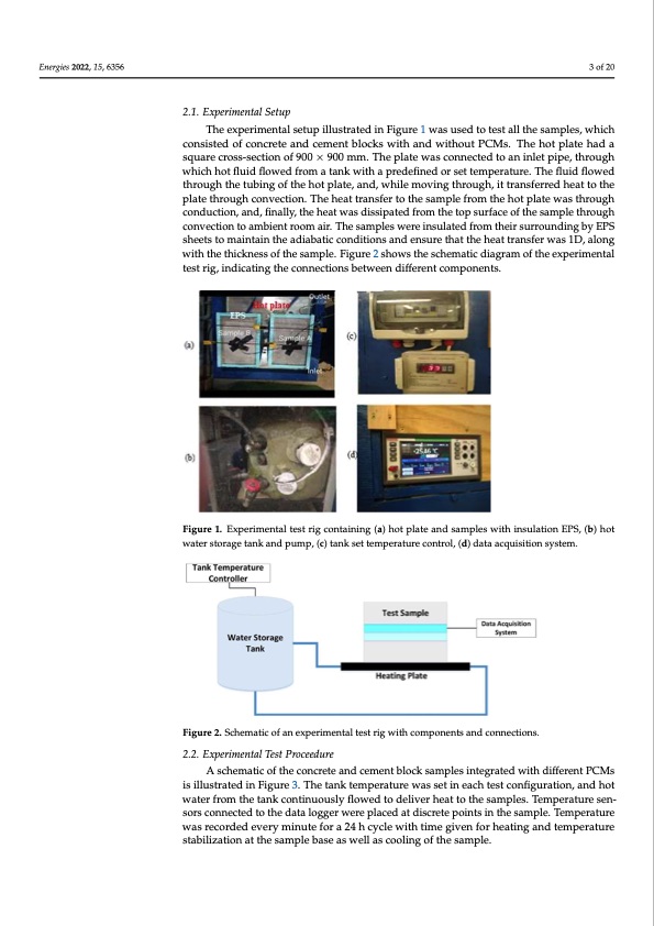
EEnneregrgieises2200222,,15,,6x3F5O6RPEERREVIEW 3 of 22 3of20 Energies 2022, 15, x FOR PEER REVIEW 3 of 22 2.1. Experimental Setup 2.1. Experimental Setup 2.1. Experimental Setup The experimental setup illustrated in Figure 1 was used to test all the samples, which TheexperimenttaallsseetutuppilillulustsrtartaetdediniFnigFuigruer1ew1awsuaseudsteodtteosttaelslttahlelstahmepsalems,pwlehsi,cwhhich consisted of concrete and cement blocks with and without PCMs. The hot plate had a cconsisted of concrreetteeaannddcceemmenetntblbolcokcskws iwthitahnadnwdiwthiotuhtoPuCt MPCs.MTsh.eThhoet phloatephlatde ahad a square cross-section of 900 mm × 900 mm. The plate was connected to an inlet pipe, ssquarecross-sectionof900×mm900×m90m0.mTmhe.Tphlaetepwlataeswcoansnceocntnedecteodantoinalnetinplieptep,itpher,ough through which hot fluid flowed from a tank with a predefined or set temperature. The wthriocuhghowtflhuicihdhflotwfleudidfrfolomwaedtafnrkomwiathtaanpkrweditehfianepdreodresfeintetdemorpesreatttuerme.pTerhaetuflrue.idThfleowed fluid flowed through the tubing of the hot plate, and, while moving through, it transferred tfhluroidufglhowtheedtuhrboiunghotfhtehteuhbiontgpolfathe,eahnodt,pwlathei,laenmd,owvihnilgetmhroovuingght,hirtoturagnhs,fietrtraendshfeeraretdtothe heat to the plate through convection. The heat transfer to the sample from the hot plate heat to the plate through convection. The heat transfer to the sample from the hot plate plate through convection. The heat transfer to the sample from the hot plate was through was through conduction, and, finally, the heat was dissipated from the top surface of the was through conduction, and, finally, the heat was dissipated from the top surface of the conduction, and, finally, the heat was dissipated from the top surface of the sample through sample through convection to ambient room air. The samples were insulated from their sample through convection to ambient room air. The samples were insulated from their convection to ambient room air. The samples were insulated from their surrounding by EPS surrounding by EPS sheets to maintain the adiabatic conditions and ensure that the heat surrounding by EPS sheets to maintain the adiabatic conditions and ensure that the heat sheets to maintain the adiabatic conditions and ensure that the heat transfer was 1D, along transfer was 1D, along with the thickness of the sample. Figure 2 shows the schematic transfer was 1D, along with the thickness of the sample. Figure 2 shows the schematic with the thickness of the sample. Figure 2 shows the schematic diagram of the experimental diagram of the experimental test rig, indicating the connections between different compo- diagram of the experimental test rig, indicating the connections between different compo- test rig, indicating the connections between different components. nents. nents. Figure 1. Experimental test rig containing (a) hot plate and samples with insulation EPS, (b) hot FFiigure1..Experriimeenntatalltetsetstrirgigcocnotnatinaingin(ga)(ah)ohtoptlaptelaatendansadmspalmespwleisthwiintshuilnatsiuonlatEiPonS,E(bP)Sh,o(bt)hot water storage tank and pump, (c) tank set temperature control, (d) data acquisition system. water storage tank and pump, (c) tank set temperature control, (d) data acquisition system. water storage tank and pump, (c) tank set temperature control, (d) data acquisition system. Figure 2. Schematic of an experimental test rig with components and connections. Figure 2. Schematic of an experimental test rig with components and connections. Figure 2. Schematic of an experimental test rig with components and connections. 2.2. Experimental Test Proceedure 22..2.. ExperimenttallTesttPrroocceeedduurere A schematic of the concrete and cement block samples integrated with different A schematic of the concrete and cement block samples integrated with different A schematic of the concrete and cement block samples integrated with different PCMs PCMs is illustrated in Figure 3. The tank temperature was set in each test configuration, PCMs is illustrated in Figure 3. The tank temperature was set in each test configuration, is illustrated in Figure 3. The tank temperature was set in each test configuration, and hot and hot water from the tank continuously flowed to deliver heat to the samples. Temper- and hot water from the tank continuously flowed to deliver heat to the samples. Temper- water from the tank continuously flowed to deliver heat to the samples. Temperature sen- ature sensors connected to the data logger were placed at discrete points in the sample. ature sensors connected to the data logger were placed at discrete points in the sample. sors connected to the data logger were placed at discrete points in the sample. Temperature was recorded every minute for a 24 h cycle with time given for heating and temperature stabilization at the sample base as well as cooling of the sample.PDF Image | PCM-Integrated Building Construction
PDF Search Title:
PCM-Integrated Building ConstructionOriginal File Name Searched:
energies-15-06356-v2.pdfDIY PDF Search: Google It | Yahoo | Bing
Turbine and System Plans CAD CAM: Special for this month, any plans are $10,000 for complete Cad/Cam blueprints. License is for one build. Try before you buy a production license. More Info
Waste Heat Power Technology: Organic Rankine Cycle uses waste heat to make electricity, shaft horsepower and cooling. More Info
All Turbine and System Products: Infinity Turbine ORD systems, turbine generator sets, build plans and more to use your waste heat from 30C to 100C. More Info
CO2 Phase Change Demonstrator: CO2 goes supercritical at 30 C. This is a experimental platform which you can use to demonstrate phase change with low heat. Includes integration area for small CO2 turbine, static generator, and more. This can also be used for a GTL Gas to Liquids experimental platform. More Info
Introducing the Infinity Turbine Products Infinity Turbine develops and builds systems for making power from waste heat. It also is working on innovative strategies for storing, making, and deploying energy. More Info
Need Strategy? Use our Consulting and analyst services Infinity Turbine LLC is pleased to announce its consulting and analyst services. We have worked in the renewable energy industry as a researcher, developing sales and markets, along with may inventions and innovations. More Info
Made in USA with Global Energy Millennial Web Engine These pages were made with the Global Energy Web PDF Engine using Filemaker (Claris) software.
Sand Battery Sand and Paraffin for TES Thermo Energy Storage More Info
| CONTACT TEL: 608-238-6001 Email: greg@infinityturbine.com | RSS | AMP |