PDF Publication Title:
Text from PDF Page: 003
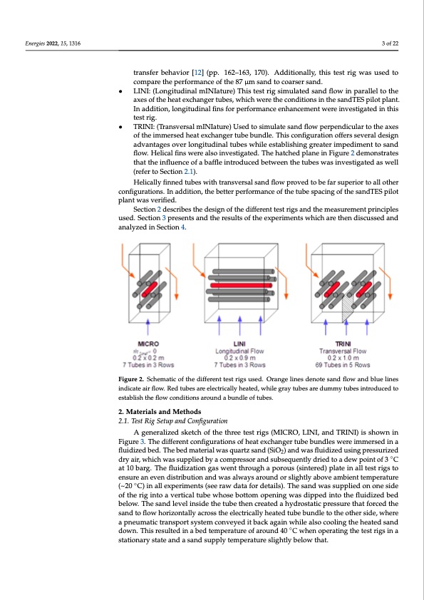
Energies 2022, 15, 1316 Kunii and Levenspiel [8] (pp. 323–329) developed a generalized model that include Mickley and Fairbank’s packet theory model for the particle convective heat transfer More recent investigations were conducted by Natale [9], Kim [10] and Pisters [11]. Some of the correlations mentioned above describe the heat transfer on any kind o 3 of 22 surface, such as Mickley and Fairbanks, while others consider tubes as the heat transfe area, such as Andeen/Glicksman and Molerus. Only some include the effect of staggere tubes in a bundle, such as Grewal. transfer behavior [12] (pp. 162–163, 170). Additionally, this test rig was used to An overall conclusion is that there is no generally accepted and undispute compare the performance of the 87 μm sand to coarser sand. correlation that would allow the proper sizing of a heat exchanger in a fluidized bed • LINI: (Longitudinal mINIature) This test rig simulated sand flow in parallel to the Additionally, none of these authors investigated the influence of a horizontal share in th axes of the heat exchanger tubes, which were the conditions in the sandTES pilot plant. sandInmaadsdsitfilonw,lonrgtihtuedeifnfaelcfitnosffoinrnperdfotrumbaens.ceenhancementwereinvestigatedinthis tAestsraing.dTES pilot plant with a mean particle diameter of 87 μm, plain tube diamete • TRINI: (Transversal mINIature) Used to simulate sand flow perpendicular to the axes of 25 mm and operating in a temperature range of 20 °C to 400 °C was designed in 201 of the immersed heat exchanger tube bundle. This configuration offers several design [12–14]. Applying all the different correlations reported by Chen, includin advantages over longitudinal tubes while establishing greater impediment to sand Kunii/Levenspiel and Martin, yields a range of the predicted heat transfer coefficien flow. Helical fins were also investigated. The hatched plane in Figure 2 demonstrates (HTC) between 250 and 600 W/m2K in this case. This high uncertainty for a horizonta that the influence of a baffle introduced between the tubes was investigated as well plain tube bundle does not even account for the influence of particle crossflow, tub (refer to Section 2.1). bundle geometry, or the influence of fins. Additionally, the influence of particle diamete Helically finned tubes with transversal sand flow proved to be far superior to all other is considered differently in practically all correlations. configurations. In addition, the better performance of the tube spacing of the sandTES pilot Since the achievable HTC is critical to the marketability of the entire sandTE plant was verified. technSeocltoiogny,2idtewscarisbedsetchiededdesitgoncofnthdeudctiffsemreanltltsecsat lreigesxapndertihmeemnetasstuoredmeetnertmprinecipthles optima utusebde.bSuecntdiolne3copnrefisgeuntrsatainodntahnedrepsualrttsicolfethsiezextpoemrimaxeinmtsiwzehtichheaHreTtChe.nFodristchuisspedurapnodse,thre analyzed in Section 4. test rigs were designed, of which a simplified sketch can be seen in Figure 2. Figure 2. Schematic of the different test rigs used. Orange lines denote sand flow and blue lines indicate air flow. Red tubes are electrically heated, while gray tubes are dummy tubes introduced to establish the flow conditions around a bundle of tubes. 2. Materials and Methods 2.1. Test Rig Setup and Configuration A generalized sketch of the three test rigs (MICRO, LINI, and TRINI) is shown in Figure 3. The different configurations of heat exchanger tube bundles were immersed in a fluidized bed. The bed material was quartz sand (SiO2) and was fluidized using pressurized dry air, which was supplied by a compressor and subsequently dried to a dew point of 3 ◦C at 10 barg. The fluidization gas went through a porous (sintered) plate in all test rigs to ensure an even distribution and was always around or slightly above ambient temperature (~20 ◦C) in all experiments (see raw data for details). The sand was supplied on one side of the rig into a vertical tube whose bottom opening was dipped into the fluidized bed below. The sand level inside the tube then created a hydrostatic pressure that forced the sand to flow horizontally across the electrically heated tube bundle to the other side, where a pneumatic transport system conveyed it back again while also cooling the heated sand down. This resulted in a bed temperature of around 40 ◦C when operating the test rigs in a stationary state and a sand supply temperature slightly below that. s r d d e r 4 g e r S ePDF Image | Heat Transfer between Finned Tubes
PDF Search Title:
Heat Transfer between Finned TubesOriginal File Name Searched:
energies-15-01316.pdfDIY PDF Search: Google It | Yahoo | Bing
Turbine and System Plans CAD CAM: Special for this month, any plans are $10,000 for complete Cad/Cam blueprints. License is for one build. Try before you buy a production license. More Info
Waste Heat Power Technology: Organic Rankine Cycle uses waste heat to make electricity, shaft horsepower and cooling. More Info
All Turbine and System Products: Infinity Turbine ORD systems, turbine generator sets, build plans and more to use your waste heat from 30C to 100C. More Info
CO2 Phase Change Demonstrator: CO2 goes supercritical at 30 C. This is a experimental platform which you can use to demonstrate phase change with low heat. Includes integration area for small CO2 turbine, static generator, and more. This can also be used for a GTL Gas to Liquids experimental platform. More Info
Introducing the Infinity Turbine Products Infinity Turbine develops and builds systems for making power from waste heat. It also is working on innovative strategies for storing, making, and deploying energy. More Info
Need Strategy? Use our Consulting and analyst services Infinity Turbine LLC is pleased to announce its consulting and analyst services. We have worked in the renewable energy industry as a researcher, developing sales and markets, along with may inventions and innovations. More Info
Made in USA with Global Energy Millennial Web Engine These pages were made with the Global Energy Web PDF Engine using Filemaker (Claris) software.
Sand Battery Sand and Paraffin for TES Thermo Energy Storage More Info
| CONTACT TEL: 608-238-6001 Email: greg@infinityturbine.com | RSS | AMP |