PDF Publication Title:
Text from PDF Page: 002
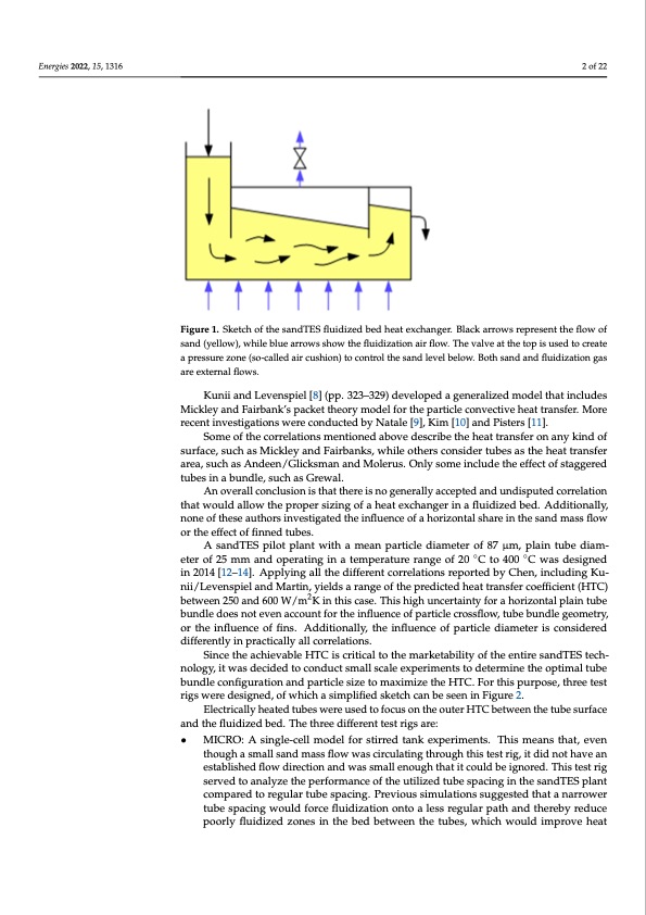
nergies 2022, 15, x FOR PEER REVIEW Energies 2022, 15, 1316 2 of 22 Figure 1. Sketch of the sandTES fluidized bed heat exchanger. Black arrows represent the flow of Figure 1. Sketch of the sandTES fluidized bed heat exchanger. Black arrows repre sand (yellow), while blue arrows show the fluidization air flow. The valve at the top is used to create sand (yellow), while blue arrows show the fluidization air flow. The valve at the top a pressure zone (so-called air cushion) to control the sand level below. Both sand and fluidization gas a pressure zone (so-called air cushion) to control the sand level below. Both sand are external flows. gas are external flows. Kunii and Levenspiel [8] (pp. 323–329) developed a generalized model that includes Mickley and Fairbank’s packet theory model for the particle convective heat transfer. More Kunii and Levenspiel [8] (pp. 323–329) developed a generalized mod recent investigations were conducted by Natale [9], Kim [10] and Pisters [11]. Mickley and Fairbank’s packet theory model for the particle convective Some of the correlations mentioned above describe the heat transfer on any kind of surface, such as Mickley and Fairbanks, while others consider tubes as the heat transfer More recent investigations were conducted by Natale [9], Kim [10] and Pis area, such as Andeen/Glicksman and Molerus. Only some include the effect of staggered Some of the correlations mentioned above describe the heat transfer tubes in a bundle, such as Grewal. surface, such as Mickley and Fairbanks, while others consider tubes as th An overall conclusion is that there is no generally accepted and undisputed correlation that would allow the proper sizing of a heat exchanger in a fluidized bed. Additionally, area, such as Andeen/Glicksman and Molerus. Only some include the effe none of these authors investigated the influence of a horizontal share in the sand mass flow tubes in a bundle, such as Grewal. or the effect of finned tubes. An overall conclusion is that there is no generally accepted an A sandTES pilot plant with a mean particle diameter of 87 μm, plain tube diam- correlation that would allow the proper sizing of a heat exchanger in a eter of 25 mm and operating in a temperature range of 20 C to 400 C was designed in 2014 [12–14]. Applying all the different correlations reported by Chen, including Ku- Additionally, none of these authors investigated the influence of a horizon nii/Levenspiel and Martin, yields a range of the predicted heat transfer coefficient (HTC) sand mass flow or the effect of finned tubes. between 250 and 600 W/m2K in this case. This high uncertainty for a horizontal plain tube bundle does not even account for the influence of particle crossflow, tube bundle geometry, A sandTES pilot plant with a mean particle diameter of 87 μm, plain or the influence of fins. Additionally, the influence of particle diameter is considered of 25 mm and operating in a temperature range of 20 °C to 400 °C was de differently in practically all correlations. [12–14]. Applying all the different correlations reported by Ch Since the achievable HTC is critical to the marketability of the entire sandTES tech- nology, it was decided to conduct small scale experiments to determine the optimal tube Kunii/Levenspiel and Martin, yields a range of the predicted heat tran bundle configuration and particle size to maximize the HTC. For this purpose, three test (HTC) between 250 and 600 W/m2K in this case. This high uncertainty f rigs were designed, of which a simplified sketch can be seen in Figure 2. plain tube bundle does not even account for the influence of particle c Electrically heated tubes were used to focus on the outer HTC between the tube surface and the fluidized bed. The three different test rigs are: bundle geometry, or the influence of fins. Additionally, the influence of pa • MICRO: A single-cell model for stirred tank experiments. This means that, even is considered differently in practically all correlations. though a small sand mass flow was circulating through this test rig, it did not have an Since the achievable HTC is critical to the marketability of the e established flow direction and was small enough that it could be ignored. This test rig technology, it was decided to conduct small scale experiments to determi served to analyze the performance of the utilized tube spacing in the sandTES plant compared to regular tube spacing. Previous simulations suggested that a narrower tube bundle configuration and particle size to maximize the HTC. For this tube spacing would force fluidization onto a less regular path and thereby reduce test rigs were designed, of which a simplified sketch can be seen in Figure poorly fluidized zones in the bed between the tubes, which would improve heat ◦◦ E a e t o e c t s e s o r r n n p 2PDF Image | Heat Transfer between Finned Tubes
PDF Search Title:
Heat Transfer between Finned TubesOriginal File Name Searched:
energies-15-01316.pdfDIY PDF Search: Google It | Yahoo | Bing
Turbine and System Plans CAD CAM: Special for this month, any plans are $10,000 for complete Cad/Cam blueprints. License is for one build. Try before you buy a production license. More Info
Waste Heat Power Technology: Organic Rankine Cycle uses waste heat to make electricity, shaft horsepower and cooling. More Info
All Turbine and System Products: Infinity Turbine ORD systems, turbine generator sets, build plans and more to use your waste heat from 30C to 100C. More Info
CO2 Phase Change Demonstrator: CO2 goes supercritical at 30 C. This is a experimental platform which you can use to demonstrate phase change with low heat. Includes integration area for small CO2 turbine, static generator, and more. This can also be used for a GTL Gas to Liquids experimental platform. More Info
Introducing the Infinity Turbine Products Infinity Turbine develops and builds systems for making power from waste heat. It also is working on innovative strategies for storing, making, and deploying energy. More Info
Need Strategy? Use our Consulting and analyst services Infinity Turbine LLC is pleased to announce its consulting and analyst services. We have worked in the renewable energy industry as a researcher, developing sales and markets, along with may inventions and innovations. More Info
Made in USA with Global Energy Millennial Web Engine These pages were made with the Global Energy Web PDF Engine using Filemaker (Claris) software.
Sand Battery Sand and Paraffin for TES Thermo Energy Storage More Info
| CONTACT TEL: 608-238-6001 Email: greg@infinityturbine.com | RSS | AMP |