PDF Publication Title:
Text from PDF Page: 007
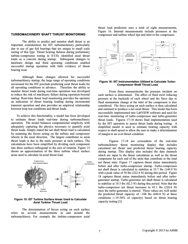
TURBOMACHINERY SHAFT THRUST MONITORING The ability to predict and monitor shaft thrust is an important consideration for IST turbomachinery particularly due to use of gas foil bearings that are unique to small scale testing of this type. Thrust bearing failures during preliminary turbine-compressor testing in S-CO2 identified axial thrust loads as a concern during startup. Subsequent changes to hardware design and fluid operating conditions enabled successful startup operation with little evidence of thrust bearing wear. Although these changes allowed for successful turbomachinery startup, the large range of operating conditions envisioned for the IST preclude predicting axial thrust loads for all operating conditions in advance. Therefore the ability to monitor thrust loads during real-time operation was developed to reduce the risk of machinery failure during operation beyond startup. Real-time thrust load monitoring provides the operator an indication of thrust bearing loading during incremental transient operation and also provides an empirical relationship between loop test conditions and thrust loads. To achieve this functionality, a model has been developed to estimate thrust loads real-time during turbomachinery operation. The model balances computational simplicity with adequately capturing the physics necessary to quantify axial thrust loads. Simply stated the net shaft thrust load is calculated by summing the forces acting on the turbine and compressor wheels in the axial direction. The largest contributor to axial thrust loads is due to the static pressure at each surface. The calculations have been simplified by dividing each component into three surfaces orthogonal to the axis of rotation. Figure 15 shows an approximation of the three turbine wheel surface areas used to calculate its axial thrust load. thrust load prediction uses a total of eight measurements, Figure 16. Internal measurements include pressures at the compressor and turbine wheel tips and inlet to the compressor. Figure 16: IST Instrumentation Utilized to Calculate Turbo- Compressor Shaft Thrust Load From these measurements the pressure incident on each surface is determined. The affect of fluid swirl reducing pressure at the backside of each wheel and the force due to fluid momentum change at the inlet of the compressor is also considered. The force acting on each surface is then calculated and summed to produce a net axial thrust. This model has been successfully implemented into LabVIEW software and used for real-time monitoring of turbo-compressor and turbo-generator thrust loads. Figures 17-18 shows final implementation used by the IST operators to assess thrust loads during testing. A simplified model is used to estimate bearing capacity with respect to shaft speed to allow the user to make a determination of margin to an over-thrust condition. Figures 17-18 are screenshots of the real-time turbomachinery thrust monitoring display that includes calculated net thrust and predicted thrust bearing capacity during startup. This display also includes the data channels which are input to the thrust calculation as well as the thrust component for each end of the units that contribute to the total net thrust state. Figure 17 captures thrust status immediately before and after turbo-compressor startup. Turbo-compressor net shaft thrust is calculated to stabilize at 33.7 lbs (149.9 N) with a peak value of 50 lbs (222.4 N) during this period. Figure 18 captures thrust status immediately before and after turbo- generator startup. Turbo-generator net shaft thrust is calculated to stabilize at 18.5 lbs (82.3 N) during this period. Note that the turbo-compressor net thrust increases to 45.1 lbs (220.6 N) once the turbo-generator is started. These values are well under the predicted thrust capacity of ~100 lbs (444.8 N) at these conditions (~19-50% of capacity) based on thrust bearing capacity testing [3]. Figure 15: IST Turbine Surface Areas Used to Calculate Axial Turbine Thrust Load The determination of forces acting on each surface relies on several measurements in and around the turbomachinery. For example the turbine-compressor axial 7 Copyright © 2013 by ASMEPDF Image | SCO2 BRAYTON CYCLE DEVELOPMENT OVERVIEW
PDF Search Title:
SCO2 BRAYTON CYCLE DEVELOPMENT OVERVIEWOriginal File Name Searched:
GT2013_94268.pdfDIY PDF Search: Google It | Yahoo | Bing
NFT (Non Fungible Token): Buy our tech, design, development or system NFT and become part of our tech NFT network... More Info
IT XR Project Redstone NFT Available for Sale: NFT for high tech turbine design with one part 3D printed counter-rotating energy turbine. Be part of the future with this NFT. Can be bought and sold but only one design NFT exists. Royalties go to the developer (Infinity) to keep enhancing design and applications... More Info
Infinity Turbine IT XR Project Redstone Design: NFT for sale... NFT for high tech turbine design with one part 3D printed counter-rotating energy turbine. Includes all rights to this turbine design, including license for Fluid Handling Block I and II for the turbine assembly and housing. The NFT includes the blueprints (cad/cam), revenue streams, and all future development of the IT XR Project Redstone... More Info
Infinity Turbine ROT Radial Outflow Turbine 24 Design and Worldwide Rights: NFT for sale... NFT for the ROT 24 energy turbine. Be part of the future with this NFT. This design can be bought and sold but only one design NFT exists. You may manufacture the unit, or get the revenues from its sale from Infinity Turbine. Royalties go to the developer (Infinity) to keep enhancing design and applications... More Info
Infinity Supercritical CO2 10 Liter Extractor Design and Worldwide Rights: The Infinity Supercritical 10L CO2 extractor is for botanical oil extraction, which is rich in terpenes and can produce shelf ready full spectrum oil. With over 5 years of development, this industry leader mature extractor machine has been sold since 2015 and is part of many profitable businesses. The process can also be used for electrowinning, e-waste recycling, and lithium battery recycling, gold mining electronic wastes, precious metals. CO2 can also be used in a reverse fuel cell with nafion to make a gas-to-liquids fuel, such as methanol, ethanol and butanol or ethylene. Supercritical CO2 has also been used for treating nafion to make it more effective catalyst. This NFT is for the purchase of worldwide rights which includes the design. More Info
NFT (Non Fungible Token): Buy our tech, design, development or system NFT and become part of our tech NFT network... More Info
Infinity Turbine Products: Special for this month, any plans are $10,000 for complete Cad/Cam blueprints. License is for one build. Try before you buy a production license. May pay by Bitcoin or other Crypto. Products Page... More Info
| CONTACT TEL: 608-238-6001 Email: greg@infinityturbine.com | RSS | AMP |