PDF Publication Title:
Text from PDF Page: 003
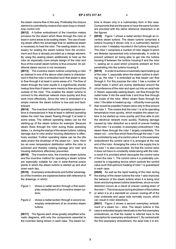
3 EP 2 573 317 A1 4 the steam volume flow in this way. Preferably the closure element is controlled by means of an open-loop or closed- loop control unit. [0012] A further embodiment of the invention makes provision for the steam which flows through the rotor at least in some areas to be sealing steam. The use of seal- ing steam offers the advantage that no additional steam is necessary to heat the rotor. The sealing steam is nec- essary for sealing the steam turbine from the environ- ment and thus is already provided as a design element. By using the sealing steam additionally to heat up the rotor an especially more simple design of the rotor and thus of the overall steam turbine is thus ensured. An ad- ditional steam source is not necessary. [0013] The inventive steam turbine comprising a rotor as claimed in one of the above-cited claims is character- ized in that the rotor is embodied such that steam is able to flow through it at least in some areas of it. The flow of steam through the rotor results in a significantly shorter heatup time than if steam were merely to flow around the outside of the rotor. This enables the steam turbine to connect to the electrical network more quickly and thus work more effectively. Since the rotor is embodied in a simple manner the steam turbine is low-cost and fault- tolerant. [0014] The inventive method for operating a steam tur- bine is characterized in that at least in defined operating states the rotor has steam flowing through it at least in some areas. The defined operating states can be the starting-up of the steam turbine for example. Because steam flows through the rotor during these operating states, i.e. during the startup of the steam turbine, rubbing damage due to rotor and/or housing distortions is effec- tively avoided. Further operating states can be the idle state and/or the shutdown of the steam tur⎯ bine. Here too an even temperature distribution within the rotor is achieved and thereby rubbing damage and rotor and housing distortions effectively prevented. [0015] The inventive rotor, the inventive steam turbine and the inventive method for operating a steam turbine are especially suitable for use in solar-thermal power plants in which the steam turbine is started up and shut down each day. [0016] Exemplary embodiments and further advantag- es of the invention are explained below with reference to the drawings, in which: bine is shown only in a rudimentary form in this case. Components that are the same or have the same function are provided with the same reference characters in all the figures. [0018] Figure 1 shows a radial section through an in- ventive steam turbine. The steam turbine comprises a turbine housing 8 shown only in a rudimentary fashion and a rotor 1 rotatably mounted in the turbine housing 8. The rotor 1 comprises a number of rotor stages 9 which are likewise represented only schematically. In order to prevent ambient air being able to get into the turbine housing 8 between the turbine housing 8 and the rotor 1, sealing air is used which prevents ambient air from penetrating into the turbine housing 8. [0019] In order to achieve a maximally rapid heating-up of the rotor 1, especially when the steam turbine is start- ing up, the rotor 1 is embodied so that steam can flow through it. For this purpose the rotor 1 has a number of radial holes 3 which are evenly distributed around the circumference of the rotor and open out into an axial hole 2. Steam, especially sealing steam, can flow through the radial holes 3 into the axial hole 2 and thus flow through the inside of the rotor. When steam flows through the rotor 1 the latter is heated up sig⎯ nificantly more quickly than would be possible if steam were only to flow around the rotor 1. This means that the rotor 1 is at its operating temperature more quickly, which enables the steam tur- bine to be started up more quickly and thus able to join the electrical network more quickly. Rubbing damage caused by rotor distortion as a result of uneven heating of the rotor 1 is avoided. In exemplary embodiment 1 the steam flows through the rotor 1 largely completely. The steam vol⎯ ume flow which flows through the rotor 1 can be controlled by way of a control valve 4. In the exemplary embodiment the control valve 4 is arranged at the rear end of the rotor. Arranging the valve in the supply line to the rotor 1 is also conceivable. So that the control valve 4 does not have to constantly rotate along with the rotor, a clutch 6 is provided which decouples the control valve 4 from the rotor 1. The control valve 4 is preferably con- nected to a regulating device which controls the control valve such that optimum heating of rotor 1 is guaranteed in each case. [0020] As well as the rapid heating of the rotor during the startup of the steam turbine the rotor 1 also improves the behavior of the steam turbine when it is being shut down and during steam turbine downtimes, since no rotor distortion occurs as a result of uneven cooling-down of the rotor 1. This is because during shutdown of the turbine or when it is at a standstill an uneven cooling-off of the rotor underside and upper side normally occurs, which can result in rotor distortions. [0021] Figure 2 shows a second exemplary embodi- ment of a steam tur⎯ bine. The steam turbine in this case is embodied largely identically to the first exemplary embodiment, so that the reader is referred here to the description for exemplary embodiment 1. By contrast with the first exemplary embodiment, the axial hole 2 is em- Figure 1 Figure 2 shows a radial section through a first exem- plary embodiment of an inventive steam tur- bine; shows a radial section through a second ex- emplary embodiment of an inventive steam turbine. The figures each show greatly simplified sche- matic diagrams, with only the components essential to the invention being shown in each case. The steam tur- [0017] 5 10 15 20 25 30 35 40 45 50 55 3PDF Image | Rotor for a steam turbine
PDF Search Title:
Rotor for a steam turbineOriginal File Name Searched:
EP2573317A1.pdfDIY PDF Search: Google It | Yahoo | Bing
NFT (Non Fungible Token): Buy our tech, design, development or system NFT and become part of our tech NFT network... More Info
IT XR Project Redstone NFT Available for Sale: NFT for high tech turbine design with one part 3D printed counter-rotating energy turbine. Be part of the future with this NFT. Can be bought and sold but only one design NFT exists. Royalties go to the developer (Infinity) to keep enhancing design and applications... More Info
Infinity Turbine IT XR Project Redstone Design: NFT for sale... NFT for high tech turbine design with one part 3D printed counter-rotating energy turbine. Includes all rights to this turbine design, including license for Fluid Handling Block I and II for the turbine assembly and housing. The NFT includes the blueprints (cad/cam), revenue streams, and all future development of the IT XR Project Redstone... More Info
Infinity Turbine ROT Radial Outflow Turbine 24 Design and Worldwide Rights: NFT for sale... NFT for the ROT 24 energy turbine. Be part of the future with this NFT. This design can be bought and sold but only one design NFT exists. You may manufacture the unit, or get the revenues from its sale from Infinity Turbine. Royalties go to the developer (Infinity) to keep enhancing design and applications... More Info
Infinity Supercritical CO2 10 Liter Extractor Design and Worldwide Rights: The Infinity Supercritical 10L CO2 extractor is for botanical oil extraction, which is rich in terpenes and can produce shelf ready full spectrum oil. With over 5 years of development, this industry leader mature extractor machine has been sold since 2015 and is part of many profitable businesses. The process can also be used for electrowinning, e-waste recycling, and lithium battery recycling, gold mining electronic wastes, precious metals. CO2 can also be used in a reverse fuel cell with nafion to make a gas-to-liquids fuel, such as methanol, ethanol and butanol or ethylene. Supercritical CO2 has also been used for treating nafion to make it more effective catalyst. This NFT is for the purchase of worldwide rights which includes the design. More Info
NFT (Non Fungible Token): Buy our tech, design, development or system NFT and become part of our tech NFT network... More Info
Infinity Turbine Products: Special for this month, any plans are $10,000 for complete Cad/Cam blueprints. License is for one build. Try before you buy a production license. May pay by Bitcoin or other Crypto. Products Page... More Info
| CONTACT TEL: 608-238-6001 Email: greg@infinityturbine.com | RSS | AMP |