PDF Publication Title:
Text from PDF Page: 003
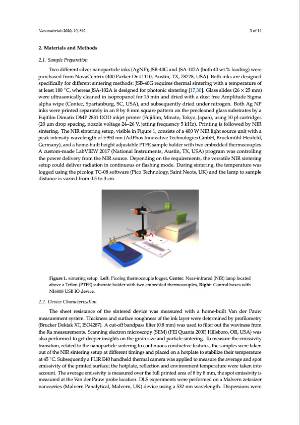
Nanomaterials 2020, 10, x FOR PEER REVIEW 3 of 14 innovative way to monitor the moment the structure becomes conductive, based on the emissivity of Nanomaterials 2020, 10, 892 3 of 14 the printed layer, is applied and compared to standard four-probe sheet resistance measurements. 2. Materials and Methods 2. Materials and Methods 2.1. Sample Preparation 2.1. Sample Preparation Two different silver nanoparticle inks (AgNP); JSB-40G and JSA-102A (both 40 wt.% loading) were Two different silver nanoparticle inks (AgNP); JSB-40G and JSA-102A (both 40 wt.% loading) purchased from NovaCentrix (400 Parker Dr #1110, Austin, TX, 78728, USA). Both inks are designed were purchased from NovaCentrix (400 Parker Dr #1110, Austin, TX, 78728, USA). Both inks are specifically for different sintering methods: JSB-40G requires thermal sintering with a temperature of designed specifically for different sintering methods: JSB-40G requires thermal sintering with a at least 180 ◦C, whereas JSA-102A is designed for photonic sintering [17,30]. Glass slides (26 × 25 mm) temperature of at least 180 °C, whereas JSA-102A is designed for photonic sintering [17,30]. Glass were ultrasonically cleaned in isopropanol for 15 min and dried with a dust free Amplitude Sigma slides (26 × 25 mm) were ultrasonically cleaned in isopropanol for 15 min and dried with a dust free alpha wipe (Contec, Spartanburg, SC, USA), and subsequently dried under nitrogen. Both Ag NP Amplitude Sigma alpha wipe (Contec, Spartanburg, SC, USA), and subsequently dried under inks were printed separately in an 8 by 8 mm square pattern on the precleaned glass substrates by a nitrogen. Both Ag NP inks were printed separately in an 8 by 8 mm square pattern on the precleaned Fujifilm Dimatix DMP 2831 DOD inkjet printer (Fujifilm, Minato, Tokyo, Japan), using 10 pl cartridges glass substrates by a Fujifilm Dimatix DMP 2831 DOD inkjet printer (Fujifilm, Minato, Tokyo, Japan), (20 μm drop spacing, nozzle voltage 24–26 V, jetting frequency 5 kHz). Printing is followed by NIR using 10 pl cartridges (20 μm drop spacing, nozzle voltage 24–26 V, jetting frequency 5 kHz). Printing sintering. The NIR sintering setup, visible in Figure 1, consists of a 400 W NIR light source unit with a is followed by NIR sintering. The NIR sintering setup, visible in Figure 1, consists of a 400 W NIR peak intensity wavelength of ±950 nm (AdPhos Innovative Technologies GmbH, Bruckmühl-Heufeld, light source unit with a peak intensity wavelength of ± 950 nm (AdPhos Innovative Technologies Germany), and a home-built height adjustable PTFE sample holder with two embedded thermocouples. GmbH, Bruckmühl-Heufeld, Germany), and a home-built height adjustable PTFE sample holder with A custom-made LabVIEW 2017 (National Instruments, Austin, TX, USA) program was controlling two embedded thermocouples. A custom-made LabVIEW 2017 (National Instruments, Austin, TX, the power delivery from the NIR source. Depending on the requirements, the versatile NIR sintering USA) program was controlling the power delivery from the NIR source. Depending on the setup could deliver radiation in continuous or flashing mode. During sintering, the temperature was requirements, the versatile NIR sintering setup could deliver radiation in continuous or flashing logged using the picolog TC-08 software (Pico Technology, Saint Neots, UK) and the lamp to sample mode. During sintering, the temperature was logged using the picolog TC-08 software (Pico distance is varied from 0.5 to 3 cm. Technology, Saint Neots, UK) and the lamp to sample distance is varied from 0.5 to 3 cm. Figure 1. sintering setup. Left: Picolog thermocouple logger, Center: Near-infrared (NIR) lamp Figure 1. sintering setup. Left: Picolog thermocouple logger, Center: Near-infrared (NIR) lamp located located above a Teflon (PTFE) substrate holder with two embedded thermocouples, Right: Control above a Teflon (PTFE) substrate holder with two embedded thermocouples, Right: Control boxes with boxes with NI6008 USB IO device. NI6008 USB IO device. 2.2. Device Characterization The sheet resistance of the sintered device was measured with a home-built Van der Pauw measuremeennttsyssytestmem. T.hTichkinceksnseasnsdasnudrfascuerrfoauceghrnoeussghofntehses inokf ltahyeriwnkereladyetrermwienreddbeyteprmofinloemdetbry (pBrroufcikloemr Deterkyta(BkrXuTc,kIeSrOD42e8k7ta).kAXcTu,tI-SoOff4b2a8n7d)p. aAsscufitlt-eorff(0b.8anmdmpa)swsafisltuesre(d0.t8omfilmter) owuatsthuesewdatvoinfeilstserfroumt theRwaamvienaessusrefmroemntsth. eScRananminegaseulercetmroennmtsi.cSrocsacnonpiyng(SeElMec)tr(oFnEImQiucaronstaco2p0y0F(,SHEiMlls)b(oFrEo,IOQRu,aUnStaA)20w0aFs, aHlsiollspbeorrfor, mOeRd, toUgSeAt)deweapserailnssoigphetsrfonrmtheedgrtoaingseitzedaenepdeprairntiscilgehstisntoernintgh.eTogrmaienassuirzethaendempisasritvicitlye tsrianntesirtinogn., rTeolatmedeatsoutrhe tnhaenoepmairstsicivleitsyinttrearninsgititonc,ornetliantueodutsocothneduncatnivoepfaeratiucrless, itnhteesrainmgptloescwonerteintuakoeuns ocountdofutchtievNeIfReastiunrtesri,ntghesestaumppaltedsifwfeerreentatikmeninogustanodftphleacNedIRonsinatheoritnpglatsetuopstatbidlizffeetrheenitrtiemipnegrsataunrde ◦ aptla4c5edC.oSnubasehqoutepnlatltyeatoFLsItRabEi4li0zheatnhdehireltdemthperemratlucraemaetra4w5 a°sCa.pSpulibesdeqtoumenetalysuareFthLeIRavEer4a0gehandhspelodt ethmeirsmsiavlitcyaomfethrae wprainstaepdpsluierdfactoe;mtheahsuotrpelathte, arevfeleractgioenananddspenovt iermonimsseivnityteomfptehreatpurrientwederesutrafkaecne;inthtoe ahcoctopulante.,Trheeflaevcteiroangeanemdiesnsiviirtoynismmeneatstuemredpeorvaeturrtheewfuerlleptraiknetendinarteoaaocfco8ubnyt8.Tmhme,atvhersapgoeteemiissivityis measuredaotvthere Vthaenfduelrl Ppariunwtepdroabrealocfat8iobny. D8 LmSmex, pthereimspeontsewmeirsesipveitryfoirsmmedeaosnuraeMd altvethrne zVeatansidzer nanoseries (Malvern Panalytical, Malvern, UK) device using a 532 nm wavelength. Dispersions werePDF Image | Nanoparticle Inkjet Inks for Near-Infrared Sintering
PDF Search Title:
Nanoparticle Inkjet Inks for Near-Infrared SinteringOriginal File Name Searched:
nanomaterials-10-00892.pdfDIY PDF Search: Google It | Yahoo | Bing
Turbine and System Plans CAD CAM: Special for this month, any plans are $10,000 for complete Cad/Cam blueprints. License is for one build. Try before you buy a production license. More Info
Waste Heat Power Technology: Organic Rankine Cycle uses waste heat to make electricity, shaft horsepower and cooling. More Info
All Turbine and System Products: Infinity Turbine ORD systems, turbine generator sets, build plans and more to use your waste heat from 30C to 100C. More Info
CO2 Phase Change Demonstrator: CO2 goes supercritical at 30 C. This is a experimental platform which you can use to demonstrate phase change with low heat. Includes integration area for small CO2 turbine, static generator, and more. This can also be used for a GTL Gas to Liquids experimental platform. More Info
Introducing the Infinity Turbine Products Infinity Turbine develops and builds systems for making power from waste heat. It also is working on innovative strategies for storing, making, and deploying energy. More Info
Need Strategy? Use our Consulting and analyst services Infinity Turbine LLC is pleased to announce its consulting and analyst services. We have worked in the renewable energy industry as a researcher, developing sales and markets, along with may inventions and innovations. More Info
Made in USA with Global Energy Millennial Web Engine These pages were made with the Global Energy Web PDF Engine using Filemaker (Claris) software.
Infinity Turbine Developing Spinning Disc Reactor SDR or Spinning Disc Reactors reduce processing time for liquid production of Silver Nanoparticles.
| CONTACT TEL: 608-238-6001 Email: greg@infinityturbine.com | RSS | AMP |