PDF Publication Title:
Text from PDF Page: 006
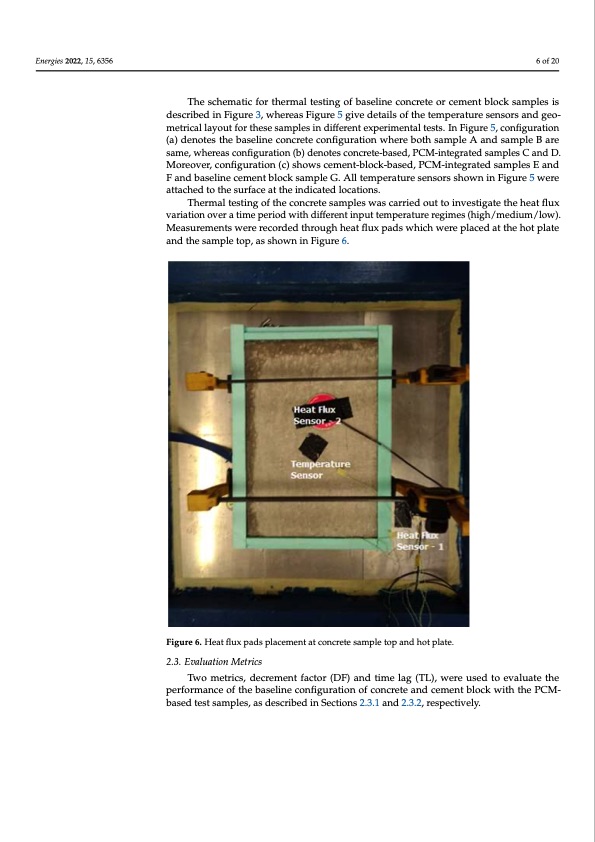
Energies 2022, 15, 6356 Figure 3 shows the baseline case for concrete followed by different combinations of dual PCMs. The constant hot climatic conditions were generated in the lab through the heat supplied by the hot plate to the sample bottom, where the bottom section was simu- lating the external surface of the building. The sides of the samples were insulated through EPS sheets, and the adiabatic boundary condition was maintained at the side walls. The top of the sample was cooled in ambient air by natural convection. Temperature was rec-6 of 20 orded at different locations, as outlined in Figure 5. T1 and T9 were on the bottom of the samples, and T5 and T13 were temperatures on the top of the samples, respectively. T14 and T17 were used at the bottom and top for the baseline cement block configuration only. The schematic for thermal testing of baseline concrete or cement block samples is The schematic for thermal testing of baseline concrete or cement block samples is de- described in Figure 3, whereas Figure 5 give details of the temperature sensors and geo- scribed in Figure 3, whereas Figure 5 give details of the temperature sensors and geomet- metrical layout for these samples in different experimental tests. In Figure 5, configuration rical layout for these samples in different experimental tests. In Figure 5, configuration (a) (a) denotes the baseline concrete configuration where both sample A and sample B are denotes the baseline concrete configuration where both sample A and sample B are same, same, whereas configuration (b) denotes concrete-based, PCM-integrated samples C and D. whereas configuration (b) denotes concrete-based, PCM-integrated samples C and D. Moreover, configuration (c) shows cement-block-based, PCM-integrated samples E and Moreover, configuration (c) shows cement-block-based, PCM-integrated samples E and F F and baseline cement block sample G. All temperature sensors shown in Figure 5 were and baseline cement block sample G. All temperature sensors shown in Figure 5 were attached to the surface at the indicated locations. attached to the surface at the indicated locations. Thermal testing of the concrete samples was carried out to investigate the heat flux Thermal testing of the concrete samples was carried out to investigate the heat flux variation over a time period with different input temperature regimes (high/medium/low). variation over a time period with different input temperature regimes (high/me- Measurements were recorded through heat flux pads which were placed at the hot plate dium/low). Measurements were recorded through heat flux pads which were placed at and the sample top, as shown in Figure 6. the hot plate and the sample top, as shown in Figure 6. Figure 6. Heat flux pads placement at concrete sample top and hot plate. Figure 6. Heat flux pads placement at concrete sample top and hot plate. 2.3. Evaluation Metrics Two metrics, decrement factor (DF) and time lag (TL), were used to evaluate the performance of the baseline configuration of concrete and cement block with the PCM- based test samples, as described in Sections 2.3.1 and 2.3.2, respectively.PDF Image | PCM-Integrated Building Construction
PDF Search Title:
PCM-Integrated Building ConstructionOriginal File Name Searched:
energies-15-06356-v2.pdfDIY PDF Search: Google It | Yahoo | Bing
Turbine and System Plans CAD CAM: Special for this month, any plans are $10,000 for complete Cad/Cam blueprints. License is for one build. Try before you buy a production license. More Info
Waste Heat Power Technology: Organic Rankine Cycle uses waste heat to make electricity, shaft horsepower and cooling. More Info
All Turbine and System Products: Infinity Turbine ORD systems, turbine generator sets, build plans and more to use your waste heat from 30C to 100C. More Info
CO2 Phase Change Demonstrator: CO2 goes supercritical at 30 C. This is a experimental platform which you can use to demonstrate phase change with low heat. Includes integration area for small CO2 turbine, static generator, and more. This can also be used for a GTL Gas to Liquids experimental platform. More Info
Introducing the Infinity Turbine Products Infinity Turbine develops and builds systems for making power from waste heat. It also is working on innovative strategies for storing, making, and deploying energy. More Info
Need Strategy? Use our Consulting and analyst services Infinity Turbine LLC is pleased to announce its consulting and analyst services. We have worked in the renewable energy industry as a researcher, developing sales and markets, along with may inventions and innovations. More Info
Made in USA with Global Energy Millennial Web Engine These pages were made with the Global Energy Web PDF Engine using Filemaker (Claris) software.
Sand Battery Sand and Paraffin for TES Thermo Energy Storage More Info
| CONTACT TEL: 608-238-6001 Email: greg@infinityturbine.com | RSS | AMP |