PDF Publication Title:
Text from PDF Page: 003
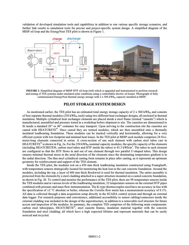
validation of developed simulation tools and capabilities in addition to run various specific storage scenarios, and further link results to simulation tools for precise and project-specific system design. A simplified diagram of the MISP oil loop and the EnergyNest TES pilot is shown in Figure 1. FIGURE 1. Simplified diagram of MISP HTF oil-loop (left) which is upgraded and instrumented to perform research and testing of TES systems under emulated solar conditions using a controllable electric oil heater. Photograph of fully commissioned EnergyNest thermal energy storage with 2 x 500 kWhth capacity installed at MISP. PILOT STORAGE SYSTEM DESIGN As mentioned earlier, the TES pilot has an estimated total energy storage capacity of 2 x 500 kWhth and consists of four separate thermal modules (250 kWhth each) using two different heat exchanger designs, all enclosed in thermal insulation. Multiple cylindrical heat exchanger elements are placed inside a steel frame (termed “cassette”) which is manufactured, assembled and pressure tested in a workshop before shipment to site. The cassettes are dimensioned to fit inside a standard 20” or 40” container for easy transport. Upon arriving to the construction site the cassettes are casted with HEATCRETE®. Once casted they are termed modules, which are then assembled onto a thermally insulated loadbearing foundation. These modules can be stacked vertically and horizontally, allowing for a very efficient system with low footprint and minimal heat losses. In the TES pilot at MISP each module comprises 24 five- meter-long elements connected in series. A cross-section of one such element with carbon steel tubes cast in HEATCRETE® is shown in Fig. 2a. For the 250 kWhth nominal capacity modules, the specific capacity of the elements (including HEATCRETE®, carbon steel tubes and HTF inside the tubes) is 43.3 kWh/m3. The tubes in each element are configured so that the HTF flows in and out of one element through two parallel U-shaped tubes. This design ensures minimal thermal stress in the axial direction of the elements since the dominating temperature gradient is in the radial direction. The thin steel cylindrical casting form remains in place after casting, as it represents an optimum geometry for reinforcement and support of the TES element. Inside the TES pilot, the modules rest on a 450 mm thick loadbearing insulation constructed using Foamglas®, with temperature sensors strategically located for monitoring the heat loss to the cast concrete foundation. Around the modules, including the top, a layer of 600 mm thick Rockwool is used for thermal insulation. The entire assembly is protected from the elements by a steel cladding attached to a super-structure mounted on a casted concrete foundation, as shown in Fig. 2b. To control and monitor the performance of the TES pilot, there are 98 temperature sensors inside the TES modules and at various levels of the loadbearing insulation, 32 temperature sensors on the external HTF pipes combined with pressure and mass flow instrumentation. The K-type thermocouples used have an accuracy in line with the specification of ±2 °C absolute or better, whereas the Coriolis flow meter has a measurement accuracy of 0.1%. All data is collected through a data acquisition setup directly in the SCADA control system and through an external data logger. For research purposes and convenience, additional accessibility to sensor cabling/connectors inside the external cladding was included in the design of the superstructure, in addition to a removable roof structure for future access and inspection of the modules. In summary, the complete TES comprises of the following main components: carbon steel tubes/pipes, HEATCRETE®, steel cassette frames, insulation material together with the concrete foundation and steel cladding; all which have a high expected lifetime and represent materials that can be easily sourced and recycled. 080011-2PDF Image | EnergyNest thermal energy storage (TES) technology
PDF Search Title:
EnergyNest thermal energy storage (TES) technologyOriginal File Name Searched:
1-4984432.pdfDIY PDF Search: Google It | Yahoo | Bing
Turbine and System Plans CAD CAM: Special for this month, any plans are $10,000 for complete Cad/Cam blueprints. License is for one build. Try before you buy a production license. More Info
Waste Heat Power Technology: Organic Rankine Cycle uses waste heat to make electricity, shaft horsepower and cooling. More Info
All Turbine and System Products: Infinity Turbine ORD systems, turbine generator sets, build plans and more to use your waste heat from 30C to 100C. More Info
CO2 Phase Change Demonstrator: CO2 goes supercritical at 30 C. This is a experimental platform which you can use to demonstrate phase change with low heat. Includes integration area for small CO2 turbine, static generator, and more. This can also be used for a GTL Gas to Liquids experimental platform. More Info
Introducing the Infinity Turbine Products Infinity Turbine develops and builds systems for making power from waste heat. It also is working on innovative strategies for storing, making, and deploying energy. More Info
Need Strategy? Use our Consulting and analyst services Infinity Turbine LLC is pleased to announce its consulting and analyst services. We have worked in the renewable energy industry as a researcher, developing sales and markets, along with may inventions and innovations. More Info
Made in USA with Global Energy Millennial Web Engine These pages were made with the Global Energy Web PDF Engine using Filemaker (Claris) software.
Sand Battery Sand and Paraffin for TES Thermo Energy Storage More Info
| CONTACT TEL: 608-238-6001 Email: greg@infinityturbine.com | RSS | AMP |