PDF Publication Title:
Text from PDF Page: 005
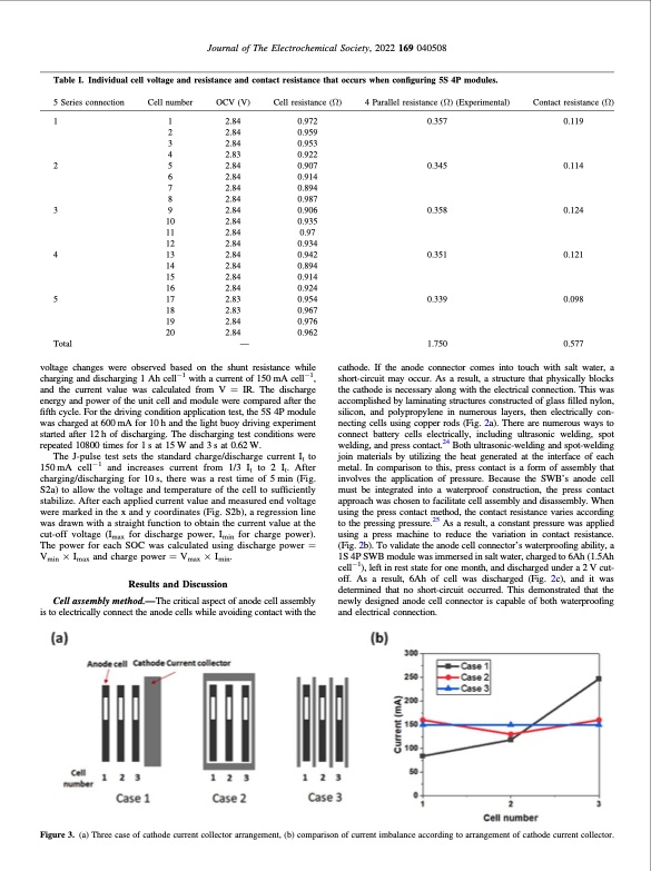
Journal of The Electrochemical Society, 2022 169 040508 Table I. Individual cell voltage and resistance and contact resistance that occurs when configuring 5S 4P modules. 5 Series connection 1 2 3 4 5 Cell number OCV (V) Cell resistance (Ω) 0.972 0.959 0.953 0.922 0.907 0.914 0.894 0.987 0.906 0.935 0.97 0.934 0.942 0.894 0.914 0.924 0.954 0.967 0.976 0.962 4 Parallel resistance (Ω) (Experimental) 0.357 0.345 0.358 0.351 0.339 1.750 Contact resistance (Ω) 0.119 0.114 0.124 0.121 0.098 0.577 Total — 1 2.84 2 2.84 3 2.84 4 2.83 5 2.84 6 2.84 7 2.84 8 2.84 9 2.84 10 2.84 11 2.84 12 2.84 13 2.84 14 2.84 15 2.84 16 2.84 17 2.83 18 2.83 19 2.84 20 2.84 voltage changes were observed based on the shunt resistance while charging and discharging 1 Ah cell−1 with a current of 150 mA cell−1, and the current value was calculated from V = IR. The discharge energy and power of the unit cell and module were compared after the fifth cycle. For the driving condition application test, the 5S 4P module was charged at 600 mA for 10 h and the light buoy driving experiment started after 12 h of discharging. The discharging test conditions were repeated 10800 times for 1s at 15W and 3s at 0.62W. The J-pulse test sets the standard charge/discharge current It to 150mA cell−1 and increases current from 1/3 It to 2 It. After charging/discharging for 10 s, there was a rest time of 5 min (Fig. S2a) to allow the voltage and temperature of the cell to sufficiently stabilize. After each applied current value and measured end voltage were marked in the x and y coordinates (Fig. S2b), a regression line was drawn with a straight function to obtain the current value at the cut-off voltage (Imax for discharge power, Imin for charge power). The power for each SOC was calculated using discharge power = Vmin × Imax and charge power = Vmax × Imin. Results and Discussion Cell assembly method.—The critical aspect of anode cell assembly is to electrically connect the anode cells while avoiding contact with the cathode. If the anode connector comes into touch with salt water, a short-circuit may occur. As a result, a structure that physically blocks the cathode is necessary along with the electrical connection. This was accomplished by laminating structures constructed of glass filled nylon, silicon, and polypropylene in numerous layers, then electrically con- necting cells using copper rods (Fig. 2a). There are numerous ways to connect battery cells electrically, including ultrasonic welding, spot welding, and press contact.24 Both ultrasonic-welding and spot-welding join materials by utilizing the heat generated at the interface of each metal. In comparison to this, press contact is a form of assembly that involves the application of pressure. Because the SWB’s anode cell must be integrated into a waterproof construction, the press contact approach was chosen to facilitate cell assembly and disassembly. When using the press contact method, the contact resistance varies according to the pressing pressure.25 As a result, a constant pressure was applied using a press machine to reduce the variation in contact resistance. (Fig. 2b). To validate the anode cell connector’s waterproofing ability, a 1S 4P SWB module was immersed in salt water, charged to 6Ah (1.5Ah cell−1), left in rest state for one month, and discharged under a 2 V cut- off. As a result, 6Ah of cell was discharged (Fig. 2c), and it was determined that no short-circuit occurred. This demonstrated that the newly designed anode cell connector is capable of both waterproofing and electrical connection. Figure 3. (a) Three case of cathode current collector arrangement, (b) comparison of current imbalance according to arrangement of cathode current collector.PDF Image | Development of Rechargeable Seawater Battery
PDF Search Title:
Development of Rechargeable Seawater BatteryOriginal File Name Searched:
Kim_2022_Electrochem-169_040508.pdfDIY PDF Search: Google It | Yahoo | Bing
Product and Development Focus for Infinity Turbine
ORC Waste Heat Turbine and ORC System Build Plans: All turbine plans are $10,000 each. This allows you to build a system and then consider licensing for production after you have completed and tested a unit.Redox Flow Battery Technology: With the advent of the new USA tax credits for producing and selling batteries ($35/kW) we are focussing on a simple flow battery using shipping containers as the modular electrolyte storage units with tax credits up to $140,000 per system. Our main focus is on the salt battery. This battery can be used for both thermal and electrical storage applications. We call it the Cogeneration Battery or Cogen Battery. One project is converting salt (brine) based water conditioners to simultaneously produce power. In addition, there are many opportunities to extract Lithium from brine (salt lakes, groundwater, and producer water).Salt water or brine are huge sources for lithium. Most of the worlds lithium is acquired from a brine source. It's even in seawater in a low concentration. Brine is also a byproduct of huge powerplants, which can now use that as an electrolyte and a huge flow battery (which allows storage at the source).We welcome any business and equipment inquiries, as well as licensing our turbines for manufacturing.| CONTACT TEL: 608-238-6001 Email: greg@infinityturbine.com | RSS | AMP |