Search Completed | Title | ORC Organic Rankine Cycle Power Systems Updates 2024
Original File Name Searched: af_orc_editorial.pdf | Google It | Yahoo | Bing
Page | 086 Paper ID: 14, Page 6 Paper ID #14, page 6 of 10
3 TEST RIG CONSTRUCTION
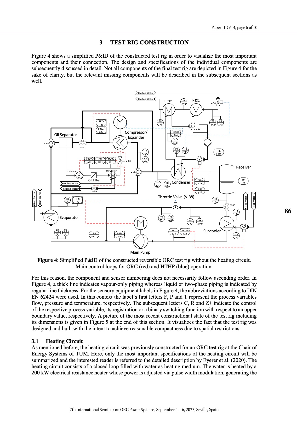
Figure 4 shows a simplified P&ID of the constructed test rig in order to visualize the most important components and their connection. The design and specifications of the individual components are subsequently discussed in detail. Not all components of the final test rig are depicted in Figure 4 for the sake of clarity, but the relevant missing components will be described in the subsequent sections as well.
V-21
Oil Separator
TRZ+ T23
PR CZ+ p23
FRC FR52
TR T47
TR T25
TRC Z+ T44
PR p44
PR p43
V-53
V-52
TRZ+ T26
PRC p26
PR p30
TR T21
PR Z+ p29
Subcooler
TR T41
Oil Pump
Cooling Water Cooling Water
PR TRC p22 T22
V-26
Receiver
LIR L21
V-51
Evaporator
PR p21
TR T31
PR
p31 TR
T30
PR Z- TRC Z+ p28 T28
V-30
TR T42
V-23
TR T24
PR p24
PRCZ+ p51
V-59
F IR FR21
TRCZ+ T51
Oil Cooler
V-63
Cooling Water Cooling Water
Compressor / Expander
HEX2
TR T46
TRC T43
HEX1
V-54
TR PR T45 p45
FR FR41
TR T27
Main Pump
Figure 4: Simplified P&ID of the constructed reversible ORC test rig without the heating circuit. Main control loops for ORC (red) and HTHP (blue) operation.
For this reason, the component and sensor numbering does not necessarily follow ascending order. In Figure 4, a thick line indicates vapour-only piping whereas liquid or two-phase piping is indicated by regular line thickness. For the sensory equipment labels in Figure 4, the abbreviations according to DIN EN 62424 were used. In this context the label’s first letters F, P and T represent the process variables flow, pressure and temperature, respectively. The subsequent letters C, R and Z+ indicate the control of the respective process variable, its registration or a binary switching function with respect to an upper boundary value, respectively. A picture of the most recent constructional state of the test rig including its dimensions is given in Figure 5 at the end of this section. It visualizes the fact that the test rig was designed and built with the intent to achieve reasonable compactness due to spatial restrictions.
3.1 Heating Circuit
As mentioned before, the heating circuit was previously constructed for an ORC test rig at the Chair of Energy Systems of TUM. Here, only the most important specifications of the heating circuit will be summarized and the interested reader is referred to the detailed description by Eyerer et al. (2020). The heating circuit consists of a closed loop filled with water as heating medium. The water is heated by a 200 kW electrical resistance heater whose power is adjusted via pulse width modulation, generating the
th
PR p25
Condens er
Throttle Valve (V-38)
Heat Source Heat Source
Tap Water
Tap Water
86
7th International Seminar on ORC Power Systems, September 4 – 6, 2023, Seville, Spain
7 International Seminar on ORC Power Systems, September 4 - 6, 2023, Seville, Spain
|