Search GE Vernonva Gas Turbine Power for Data Center Publications search was updated real-time via Filemaker on:
Page | 019 Doc Name : GER-3620 Rev P Released Date : 2021/03/15 Page 19 of 60
hours after cool-down is completed, then it may be taken
off of turning gear.
Figure F-1 also provides guidelines for hot restarts. When
an immediate restart is required, it is recommended that
the rotor be placed on turning gear for one hour following
a trip from load, trip from full speed no load, or normal
shutdown. This will allow transient thermal stresses to
subside before superimposing a startup transient. If the
machine must be restarted in less than one hour, a start
factor of 2 will apply.
Longer periods of turning gear operation may be necessary
prior to a cold start or hot restart if bow is detected.
Vibration data taken while at crank speed can be used to
confirm that rotor bow is at acceptable levels and the start
sequence can be initiated. Users should reference the O&M
Manual and appropriate TILs for specific instructions and
information for their units.
Combustion Parts
From hardware configuration standpoint, GE Vernova
combustion hardware configuration include transition
pieces, combustion liners, combustion unibodies,
combustor cones, flow sleeves, head-end assemblies
containing fuel nozzles and cartridges, end caps and end
covers, and assorted other hardware parts including cross-
fire tubes, spark plugs and flame detectors. In addition,
there are various fuel and air delivery components such as
purge or check valves and flexible hoses.
GE Vernova offers several types of combustion systems
configurations: Standard combustors, Multi-Nozzle Quiet
Combustors (MNQC), Integrated Gasification Combined
Cycle (IGCC) combustors, and Dry Low NOx (DLN)
combustors. The GE Vernova Annular/Silo Fleet offers further
combustion systems: Silo combustors with single burners
(SB) for Natural or LBTu gases or multiple EnVironmental
burners (EV), furthermore Annular combustors with
EnVironmental Burners (EV), Advanced EnVironmental
Combustor
Type
FSNL Base Load
Burners (AEV) and Sequential EnVironmental Burners (SEV).
Each of the combustion configurations mentioned above,
has specific gas or liquid fuel operating characteristics
that affect differently combustion hardware factored
maintenance intervals and refurbishment requirements.
Gas turbines fitted with DLN combustion systems operate
in incremental combustion modes to reach to base load
operation. A combustion mode constitutes a range of
turbine load where fuel delivery in combustion cans is
performed via certain combination of fuel nozzles or fuel
circuits within the fuel nozzles. For example, for DLN 2.6
combustion systems, mode 3 refers to the load range when
fuel is being delivered to PM 1 (Premix 1) and PM 2 (Premix
2) fuel nozzles through gas control valves PM 1 and PM 2.
Combustion modes change when turbine load, and
consequently combustion reference temperature value
(TTRF1 or CRT) crosses threshold values defining the
initiation of next combustion mode.
•
•
Continuous mode operation mentioned in this section
refers to intentional turbine operation in a certain
combustion mode for longer than what typically takes
during normal startup/shutdown.
Extended mode operation mentioned in this
sections is possible in DLN1 or 1+ and DLN2 or
2+ combustion configuration only, where the
controls logics can be forced to extend a Lean-Lean
Mode or Piloted Premixed Mode beyond the turbine
load corresponding to a normal combustion mode
transfer (as defined via TTRF1 or CRT values).
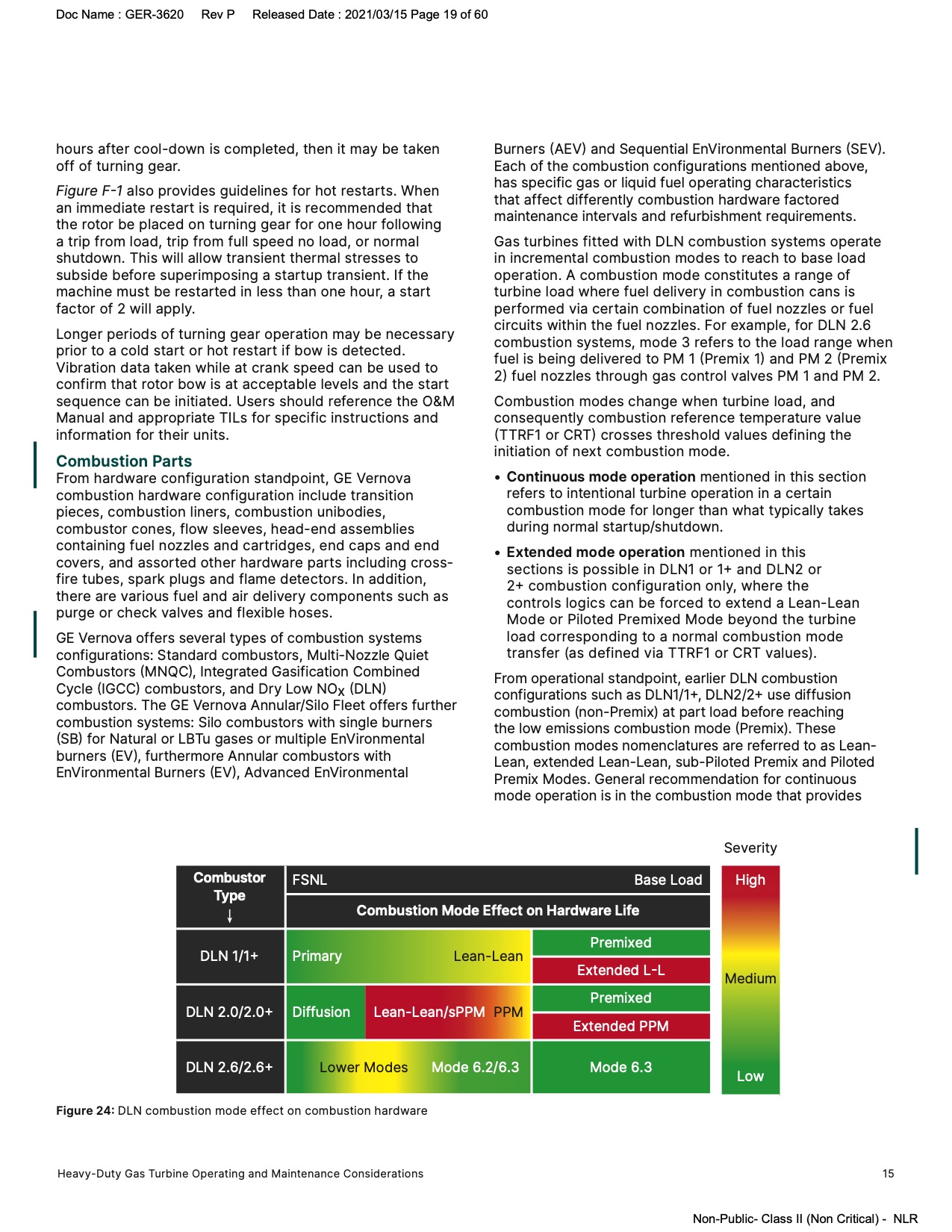
From operational standpoint, earlier DLN combustion
configurations such as DLN1/1+, DLN2/2+ use diffusion
combustion (non-Premix) at part load before reaching
the low emissions combustion mode (Premix). These
combustion modes nomenclatures are referred to as Lean-
Lean, extended Lean-Lean, sub-Piloted Premix and Piloted
Premix Modes. General recommendation for continuous
mode operation is in the combustion mode that provides
Severity
High
Combustion Mode Effect on Hardware Life
Premixed
DLN 1/1+ Primary
Lean-Lean
Extended L-L
Medium
Premixed
DLN 2.0/2.0+ Diffusion Lean-Lean/sPPM
PPM
Extended PPM
DLN 2.6/2.6+ Lower Modes Mode 6.2/6.3 Mode 6.3
Low
Figure 24: DLN combustion mode effect on combustion hardware
Heavy-Duty Gas Turbine Operating and Maintenance Considerations 15
Non-Public- Class II (Non Critical) - NLR |