PDF Publication Title:
Text from PDF Page: 003
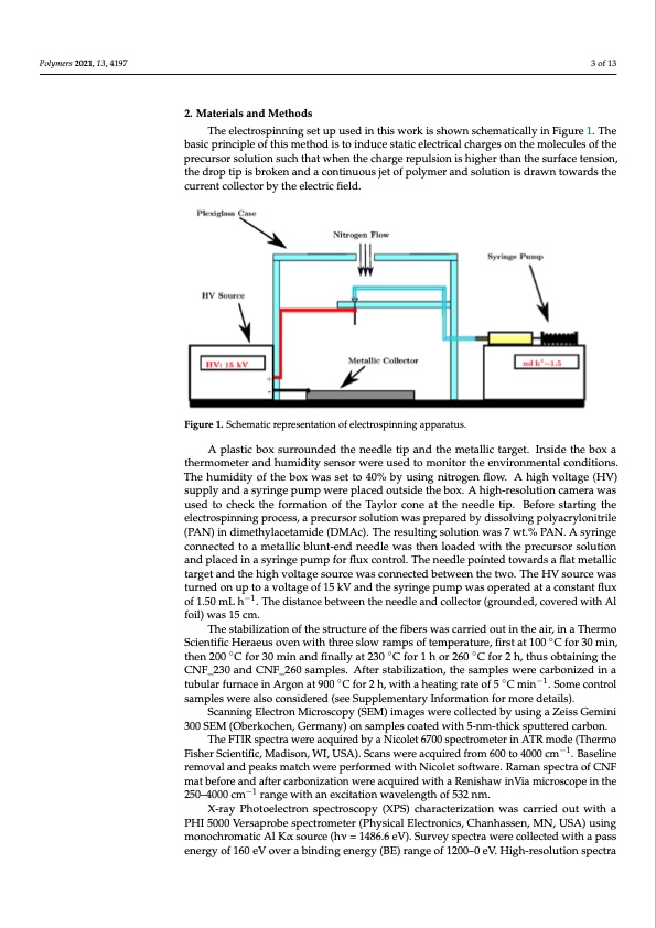
Polymers 2021, 13, 4197 3 of 13 Polymers 2021, 13, x FOR PEER REVIEW 3 of 12 2. Materials and Methods The electrospinning set up used in this work is shown schematically in Figure 1.. The basic principle of this method is to induce static electrical charges on the molecules of the precursor solution such that when the charge repulsion is higher than the surface tension, the drop tip is broken and a continuous jet of polymer and solution is drawn towards the current collector by the electric fifield. Figure 1. Schematic representation of electrospinning apparatus. A plastic box surrounded the needle tip and the metallic target. Inside the box a A plastic box surrounded the needle tip and the metallic target. Inside the box a thermometer and humidity sensor were used to monitor the environmental conditions. thermometer and humidity sensor were used to monitor the environmental conditions. The humidity of the box was set to 40% by using nitrogen flow. A high voltage (HV) The humidity of the box was set to 40% by using nitrogen flow. A high voltage (HV) supply and a syringe pump were placed outside the box. A high-resolution camera was supply and a syringe pump were placed outside the box. A high-resolution camera was used to check the formation of the Taylor cone at the needle tip. Before starting the used to check the formation of the Taylor cone at the needle tip. Before starting the electrospinning process, a precursor solution was prepared by dissolving polyacrylonitrile electrospinning process, a precursor solution was prepared by dissolving (PAN) in dimethylacetamide (DMAc). The resulting solution was 7 wt.% PAN. A syringe polyacrylonitrile (PAN) in dimethylacetamide (DMAc). The resulting solution was 7 wt.% connected to a metallic blunt-end needle was then loaded with the precursor solution PAN. A syringe connected to a metallic blunt-end needle was then loaded with the and placed in a syringe pump for flux control. The needle pointed towards a flat metallic precursor solution and placed in a syringe pump for flux control. The needle pointed target and the high voltage source was connected between the two. The HV source was towards a flat metallic target and the high voltage source was connected between the two. turned on up to a voltage of 15 kV and the syringe pump was operated at a constant flux The HV source was turned on up to a voltage of 15 kV and the syringe pump was operated of 1.50 mL h−1. The distance between the needle and collector (grounded, covered with Al at a constant flux of 1.50 mL h−1. The distance between the needle and collector (grounded, foil) was 15 cm. covered with Al foil) was 15 cm. The stabilization of the structure of the fibers was carried out in the air, in a Thermo The stabilization of the structure of the fibers was carried out in the air, in a Thermo Scientific Heraeus oven with three slow ramps of temperature, first at 100 ◦C for 30 min, Scientific Heraeus oven with three slow ramps of temperature, first at 100 °C for 30 min, then 200 ◦C for 30 min and finally at 230 ◦C for 1 h or 260 ◦C for 2 h, thus obtaining the then 200 °C for 30 min and finally at 230 °C for 1 h or 260 °C for 2 h, thus obtaining the CNF_230 and CNF_260 samples. After stabilization, the samples were carbonized in a CNF_230 and CNF_260 samples. After stabilization, the samples were carbonized in a tubular furnace in Argon at 900 ◦C for 2 h, with a heating rate of 5 ◦C min−1. Some control tubular furnace in Argon at 900 °C for 2 h, with a heating rate of 5 °C min−1. Some control samples were also considered (see Supplementary Information for more details). samples were also considered (see Supplementary Information for more details). Scanning Electron Microscopy (SEM) images were collected by using a Zeiss Gemini Scanning Electron Microscopy (SEM) images were collected by using a Zeiss Gemini 300 SEM (Oberkochen, Germany) on samples coated with 5-nm-thick sputtered carbon. 300 SEM (Oberkochen, Germany) on samples coated with 5-nm-thick sputtered carbon. The FTIR spectra were acquired by a Nicolet 6700 spectrometer in ATR mode (Thermo The FTIR spectra were acquired by a Nicolet 6700 spectrometer in −A1TR mode Fisher Scientific, Madison, WI, USA). Scans were acquired from 600 to 4000 cm . Baseline (Thermo Fisher Scientific, Madison, WI, USA). Scans were acquired from 600 to 4000 cm−1. removal and peaks match were performed with Nicolet software. Raman spectra of CNF Baseline removal and peaks match were performed with Nicolet software. Raman spectra mat before and after carbonization were acquired with a Renishaw inVia microscope in the of CNF mat−1before and after carbonization were acquired with a Renishaw inVia 250–4000 cm range with an excitation wavelength of 532 nm. microscope in the 250–4000 cm−1 range with an excitation wavelength of 532 nm. X-ray Photoelectron spectroscopy (XPS) characterization was carried out with a X-ray Photoelectron spectroscopy (XPS) characterization was carried out with a PHI PHI 5000 Versaprobe spectrometer (Physical Electronics, Chanhassen, MN, USA) using 5000 Versaprobe spectrometer (Physical Electronics, Chanhassen, MN, USA) using monochromatic Al Kα source (hν = 1486.6 eV). Survey spectra were collected with a pass monochromatic Al Kα source (hν = 1486.6 eV). Survey spectra were collected with a pass energy of 160 eV over a binding energy (BE) range of 1200–0 eV. High-resolution spectra energy of 160 eV over a binding energy (BE) range of 1200–0 eV. High-resolution spectraPDF Image | Effect of Thermal Stabilization on PAN-Derived Electrospun Carbon Nanofibers
PDF Search Title:
Effect of Thermal Stabilization on PAN-Derived Electrospun Carbon NanofibersOriginal File Name Searched:
polymers-13-04197-v2.pdfDIY PDF Search: Google It | Yahoo | Bing
Sulfur Deposition on Carbon Nanofibers using Supercritical CO2 Sulfur Deposition on Carbon Nanofibers using Supercritical CO2. Gamma sulfur also known as mother of pearl sulfur and nacreous sulfur... More Info
CO2 Organic Rankine Cycle Experimenter Platform The supercritical CO2 phase change system is both a heat pump and organic rankine cycle which can be used for those purposes and as a supercritical extractor for advanced subcritical and supercritical extraction technology. Uses include producing nanoparticles, precious metal CO2 extraction, lithium battery recycling, and other applications... More Info
| CONTACT TEL: 608-238-6001 Email: greg@infinityturbine.com | RSS | AMP |