Search Gas Turbine Power for Data Center Publications search was updated real-time via Filemaker on:
Page | 002 In the porous-only zone true surface combustion (A) is realized. Under lean conditions this will manifest as very short laminar
flamelets, but under rich conditions the surface combustion will become a diffusion-dominated reaction stabilized just over a millimeter
above the metal matrix, which proceeds without visible flame and heats the outer surface of the mat to incandescence. This type of
radiant surface combustion can be seen between the laminar flamelets to the right of figure 1.
Portions of the metal fiber mat are perforated to allow higher mass flux (B). In these zones stretched laminar flames are
established that are anchored by the adjacent surface combustion. This produces the distinctive flame pattern seen in the right-hand
picture of figure 1. The specific perforation arrangement and pattern control the size and shape of the laminar flamelets. The perforated
zones operate at flow velocities of up to 10 times the laminar flame speed producing a factor of ten stretch of the flame surface and
resulting in a large laminar flamelets. The alternating arrangement of laminar blue flames and surface combustion, allows high firing
rates to be achieved before flame liftoff occurs, with the surface combustion stabilizing the long laminar flames by providing a pool of
hot combustion radicals at the flame edges.
At atmospheric operation, nominal injector output would be 3.15 MW/m2 (1.0 million Btu/hr/ft2), so an injector with a fired area
of .047 m2 (0.5 ft2) would have a capacity of 146.5 kW (500,000 Btu/hr). Assuming the firing rate of the injector increases linearly with
pressure, the SFR remains constant as pressure increases. This results in a compact injector size for a given capacity in high pressure
systems. Therefore the 146.5 kW (500,000 Btu/hr) injector at 0.1 MPa (1 atm) becomes nominally a 1,465 kW (5 million Btu/hr injector)
at 1 Mpa (10 atm). Put another way, based on a gas turbine with a heat rate of 10,000 Btu/kilowatt-hour and a combustion pressure of
10 atmospheres, only about one square foot of injector surface area would be required for every megawatt of gas turbine output.
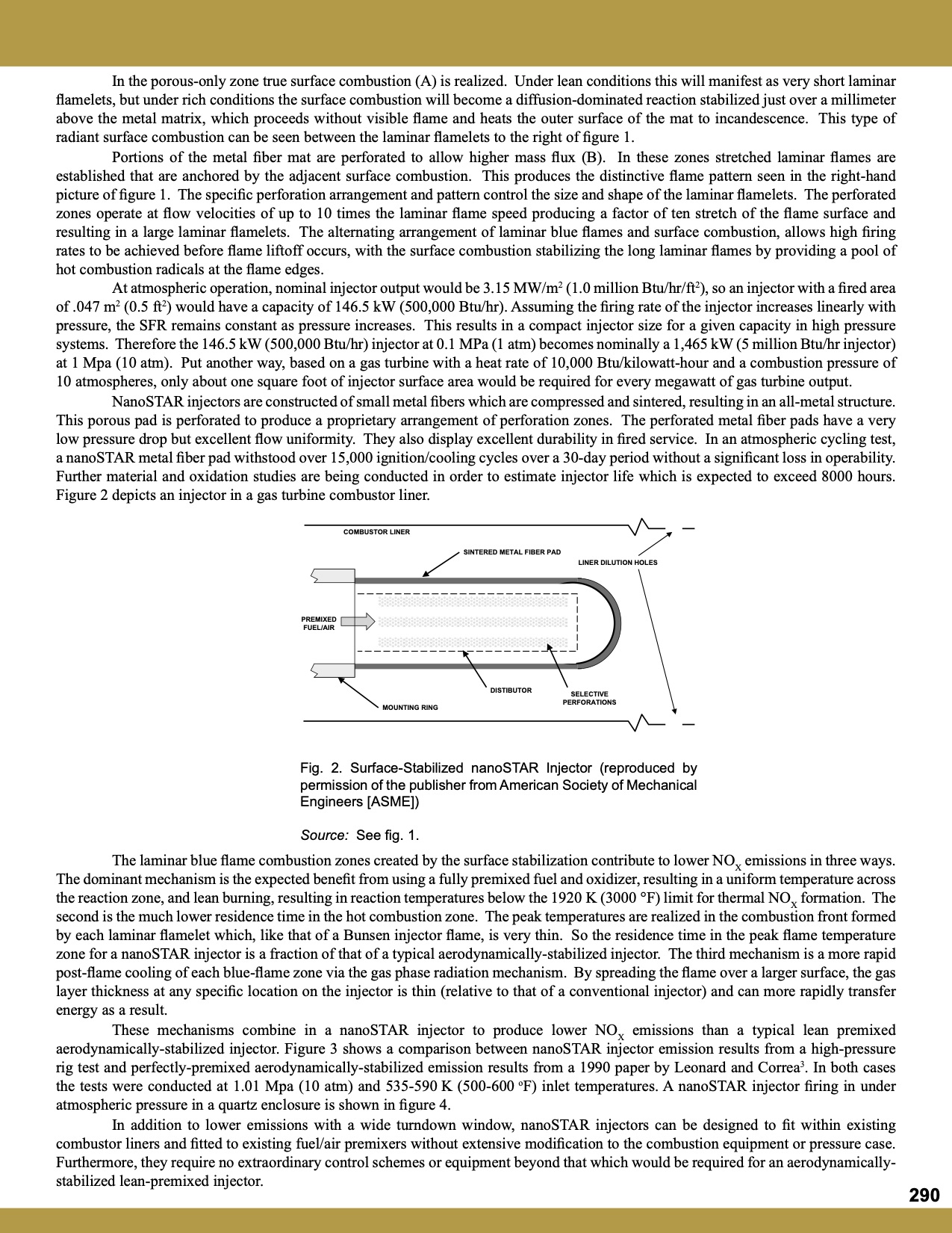
NanoSTAR injectors are constructed of small metal fibers which are compressed and sintered, resulting in an all-metal structure.
This porous pad is perforated to produce a proprietary arrangement of perforation zones. The perforated metal fiber pads have a very
low pressure drop but excellent flow uniformity. They also display excellent durability in fired service. In an atmospheric cycling test,
a nanoSTAR metal fiber pad withstood over 15,000 ignition/cooling cycles over a 30-day period without a significant loss in operability.
Further material and oxidation studies are being conducted in order to estimate injector life which is expected to exceed 8000 hours.
Figure 2 depicts an injector in a gas turbine combustor liner.
COMBUSTOR LINER
SINTERED METAL FIBER PAD
LINER DILUTION HOLES
PREMIXED
FUEL/AIR
DISTIBUTOR
SELECTIVE
PERFORATIONS
MOUNTING RING
Fig. 2. Surface-Stabilized nanoSTAR Injector (reproduced by
permission of the publisher from American Society of Mechanical
Engineers [ASME])
Source: See fig. 1.
The laminar blue flame combustion zones created by the surface stabilization contribute to lower NOX emissions in three ways.
The dominant mechanism is the expected benefit from using a fully premixed fuel and oxidizer, resulting in a uniform temperature across
the reaction zone, and lean burning, resulting in reaction temperatures below the 1920 K (3000 °F) limit for thermal NOX formation. The
second is the much lower residence time in the hot combustion zone. The peak temperatures are realized in the combustion front formed
by each laminar flamelet which, like that of a Bunsen injector flame, is very thin. So the residence time in the peak flame temperature
zone for a nanoSTAR injector is a fraction of that of a typical aerodynamically-stabilized injector. The third mechanism is a more rapid
post-flame cooling of each blue-flame zone via the gas phase radiation mechanism. By spreading the flame over a larger surface, the gas
layer thickness at any specific location on the injector is thin (relative to that of a conventional injector) and can more rapidly transfer
energy as a result.
These mechanisms combine in a nanoSTAR injector to produce lower NOX emissions than a typical lean premixed
aerodynamically-stabilized injector. Figure 3 shows a comparison between nanoSTAR injector emission results from a high-pressure
rig test and perfectly-premixed aerodynamically-stabilized emission results from a 1990 paper by Leonard and Correa3. In both cases
the tests were conducted at 1.01 Mpa (10 atm) and 535-590 K (500-600 oF) inlet temperatures. A nanoSTAR injector firing in under
atmospheric pressure in a quartz enclosure is shown in figure 4.
In addition to lower emissions with a wide turndown window, nanoSTAR injectors can be designed to fit within existing
combustor liners and fitted to existing fuel/air premixers without extensive modification to the combustion equipment or pressure case.
Furthermore, they require no extraordinary control schemes or equipment beyond that which would be required for an aerodynamically-
stabilized lean-premixed injector.
290 |