Search Gas Turbine Power for Data Center Publications search was updated real-time via Filemaker on:
Page | 018 6.4. FUEL SUPPLY SYSTEM
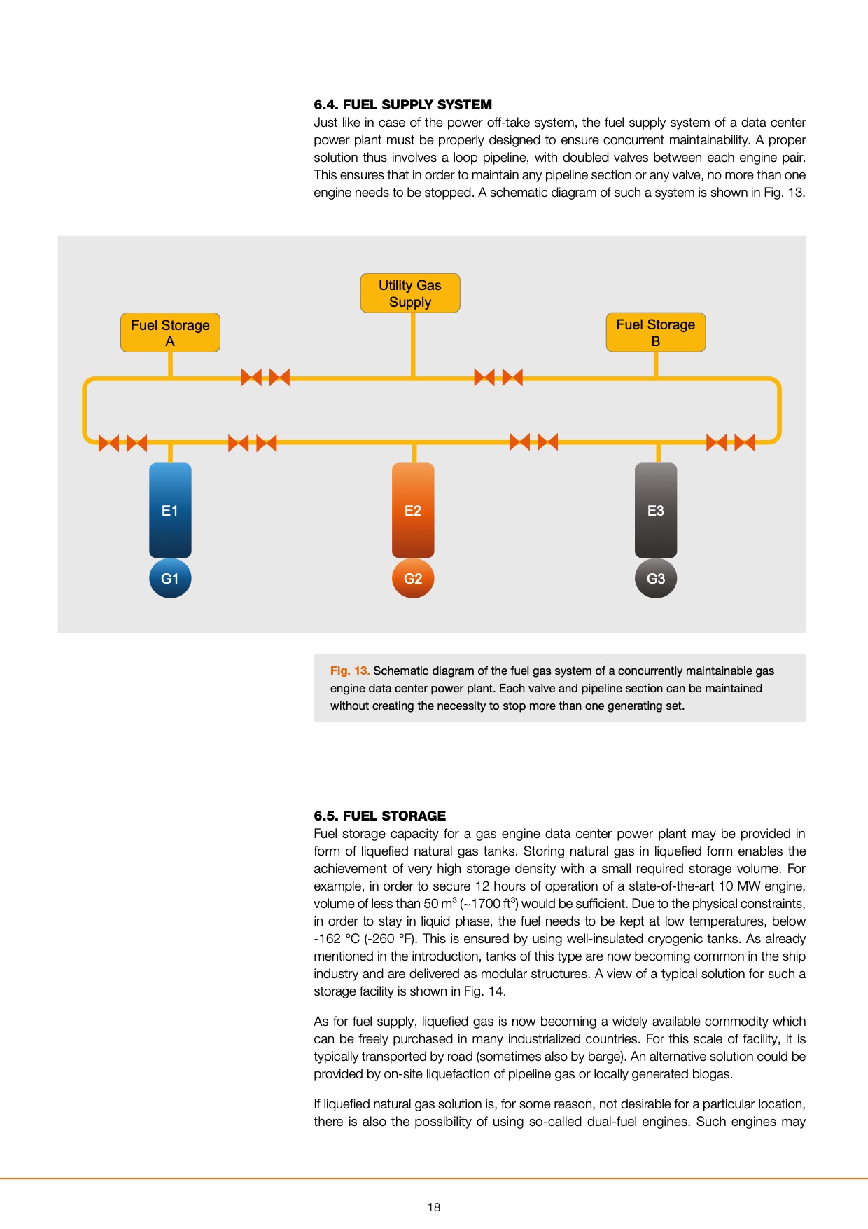
Just like in case of the power off-take system, the fuel supply system of a data center
power plant must be properly designed to ensure concurrent maintainability. A proper
solution thus involves a loop pipeline, with doubled valves between each engine pair.
This ensures that in order to maintain any pipeline section or any valve, no more than one
engine needs to be stopped. A schematic diagram of such a system is shown in Fig. 13.
Utility Gas
Supply
Fuel Storage
A
Fuel Storage
B
E1 E2 E3
G1 G2 G3
Fig. 13. Schematic diagram of the fuel gas system of a concurrently maintainable gas
engine data center power plant. Each valve and pipeline section can be maintained
without creating the necessity to stop more than one generating set.
6.5. FUEL STORAGE
Fuel storage capacity for a gas engine data center power plant may be provided in
form of liquefied natural gas tanks. Storing natural gas in liquefied form enables the
achievement of very high storage density with a small required storage volume. For
example, in order to secure 12 hours of operation of a state-of-the-art 10 MW engine,
volume of less than 50 m³ (~1700 ft³) would be sufficient. Due to the physical constraints,
in order to stay in liquid phase, the fuel needs to be kept at low temperatures, below
-162 °C (-260 °F). This is ensured by using well-insulated cryogenic tanks. As already
mentioned in the introduction, tanks of this type are now becoming common in the ship
industry and are delivered as modular structures. A view of a typical solution for such a
storage facility is shown in Fig. 14.
As for fuel supply, liquefied gas is now becoming a widely available commodity which
can be freely purchased in many industrialized countries. For this scale of facility, it is
typically transported by road (sometimes also by barge). An alternative solution could be
provided by on-site liquefaction of pipeline gas or locally generated biogas.
If liquefied natural gas solution is, for some reason, not desirable for a particular location,
there is also the possibility of using so-called dual-fuel engines. Such engines may
18 |