Search Gas Turbine Power for Data Center Publications search was updated real-time via Filemaker on:
Page | 006 942 APPENDIX K
and stator blades of each stage and include flow angles, diffusion factors,
degree of reactions, pressures, Mach numbers, temperatures, velocities,
number of blades, and blade centrifugal stress.
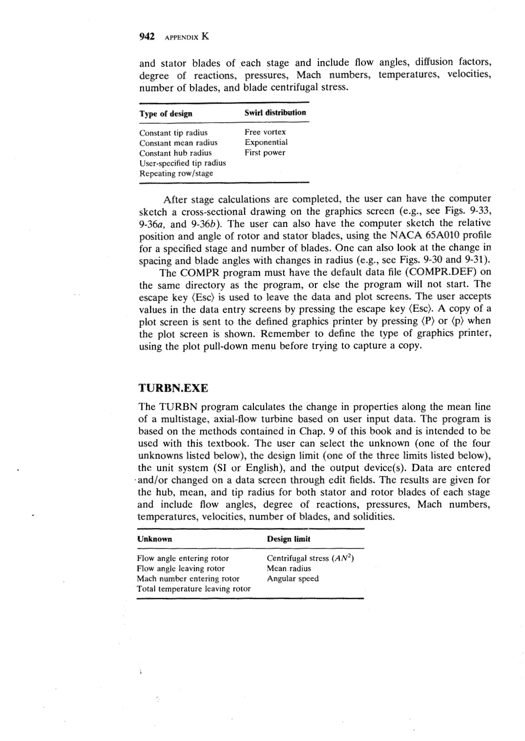
Type of design
Swirl distribution
Constant tip radius
Constant mean radius
Constant hub radius
User-specified tip radius
Repeating row/stage
Free vortex
Exponential
First power
After stage calculations are completed, the user can have the computer
sketch a cross-sectional drawing on the graphics screen (e.g., see Figs. 9-33,
9-36a, and 9-36b ). The user can also have the computer sketch the relative
position and angle of rotbr and stator blades, using the NACA 65A010 profile
for a specified stage and number of blades. One can also look at the change in
spacing and blade angles with changes in radius ( e.g., see Figs. 9-30 and 9-31 ).
The COMPR program must have the default data file (COMPR.DEF) on
the same directory as the program, or else the program will not start. The
escape key (Esc) is used to leave the data and plot screens. The user accepts
values in the data entry screens by pressing the escape key (Esc). A copy of a
plot screen is sent to the defined graphics printer by pressing (P) or (p) when
the plot screen is shown. Remember to define the type of graphics printer,
using the plot pull-down menu before trying to capture a copy.
TURBN.EXE
The TURBN program calculates the change in properties along the mean line
of a multistage, axial-flow turbine based on user input data. The program is
based on the methods contained in Chap. 9 of this book and is intended to be
used with this textbook. The user can select the unknown ( one of the four
unknowns listed below), the design limit ( one of the three limits listed below),
the unit system (SI or English), and the output device(s). Data are entered
·and/or changed on a data screen through edit fields. The results are given for
the hub, mean, and tip radius for both stator and rotor blades of each stage
and include flow angles, degree of reactions, pressures, Mach numbers,
temperatures, velocities, number of blades, and solidities.
Unknown
Design limit
Flow angle entering rotor
Flow angle leaving rotor
Mach number entering rotor
Total temperature leaving rotor
Centrifugal stress (AN2 )
Mean radius
Angular speed |