Search Gas Turbine Power for Data Center Publications search was updated real-time via Filemaker on:
Page | 006 M5A Series Gas Turbine Generator Specifications
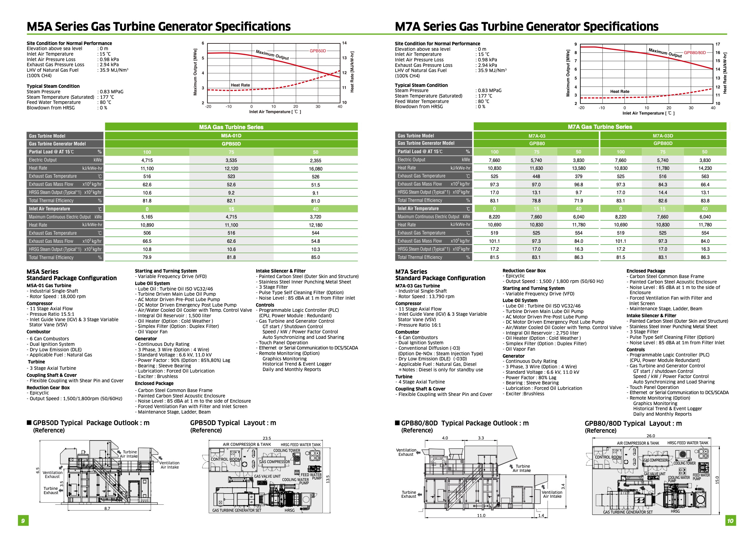
Site Condition for Normal Performance
Elevation above sea level Inlet Air Temperature Inlet Air Pressure Loss Exhaust Gas Pressure Loss LHV of Natural Gas Fuel (100% CH4)
: 0 m
: 15 °C
: 0.98 kPa
: 2.94 kPa
: 35.9 MJ/Nm3
Typical Steam Condition
Steam Pressure : 0.83 MPaG
Steam Temperature (Saturated) : 177 °C
Feed Water Temperature M5 Series
: 80 °C
Blowdown from HRSG : 0 %
M5A Gas Turbine Series
M5A-01D
GPB50D
4,715
3,535
2,355
11,100
12,120
16,080
516
523
526
62.6
52.6
51.5
10.6
9.2
9.1
81.8
82.1
81.0
0
15
5,165
4,715
3,720
10,890
11,100
12,180
506
516
544
66.5
62.6
54.8
10.8
10.6
10.3
79.9
81.8
85.0
M5A Series
Standard Package Configuration
M5A-01 Gas Turbine
- Industrial Single-Shaft
- Rotor Speed : 18,000 rpm
Compressor
- 11 Stage Axial Flow
- Pressue Ratio 15.5:1
- Inlet Guide Vane (IGV) & 3 Stage Variable
Stator Vane (VSV)
Combustor
- 6 Can Combustors
- Dual Ignition System
- Dry Low Emission (DLE)
- Applicable Fuel : Natural Gas
Turbine
- 3 Stage Axial Turbine
Coupling Shaft & Cover
- Flexible Coupling with Shear Pin and Cover
Reduction Gear Box
- Epicyclic
- Output Speed : 1,500/1,800rpm (50/60Hz)
Starting and Turning System
- Variable Frequency Drive (VFD)
Lube Oil System
- Lube Oil : Turbine Oil ISO VG32/46
- Turbine Driven Main Lube Oil Pump
- AC Motor Driven Pre-Post Lube Pump
- DC Motor Driven Emergency Post Lube Pump
- Air/Water Cooled Oil Cooler with Temp. Control Valve
- Integral Oil Reservoir : 1,500 liter
- Oil Heater (Option : Cold Weather )
- Simplex Filter (Option : Duplex Filter)
- Oil Vapor Fan
Generator
- Continuous Duty Rating
- 3 Phase, 3 Wire (Option : 4 Wire)
- Standard Voltage : 6.6 kV, 11.0 kV
- Power Factor : 90% (Option : 85%,80%) Lag
- Bearing : Sleeve Bearing
- Lubrication : Forced Oil Lubrication
- Exciter : Brushless
Enclosed Package
- Carbon Steel Common Base Frame
- Painted Carbon Steel Acoustic Enclosure
- Noise Level : 85 dBA at 1 m to the side of Enclosure
- Forced Ventilation Fan with Filter and Inlet Screen
- Maintenance Stage, Ladder, Beam
Intake Silencer & Filter
- Painted Carbon Steel (Outer Skin and Structure)
- Stainless Steel Inner Punching Metal Sheet
- 3 Stage Filter
- Pulse Type Self Cleaning Filter (Option)
- Noise Level : 85 dBA at 1 m from Filter inlet
Controls
- Programmable Logic Controller (PLC)
(CPU, Power Module : Redundant)
- Gas Turbine and Generator Control
GT start / Shutdown Control
Speed / kW / Power Factor Control
Auto Synchronizing and Load Sharing
- Touch Panel Operation
- Ethernet or Serial Communication to DCS/SCADA
- Remote Monitoring (Option)
Graphics Monitoring
Historical Trend & Event Logger
Daily and Monthly Reports
GPB50D Typical Package Outlook : m
(Reference)
GPB50D Typical Layout : m
(Reference)
23.5
AIR COMPRESSOR & TANK
HRSG FEED WATER TANK
COOLING TOWER
Turbine
Air Intak e
CONTROL ROOM
Ventilation
Air Intake
GAS COMPRESSOR
6.5
GAS VALVE UNIT
FEED WATER
COOLING WATER
PUMP
PUMP
GAS TURBINE GENERATOR SET
HRSG
V entilation
Exhaust
3.5
Turbine
Exhaust
13.5
8.7
9
M7A Series Gas Turbine Generator Specifications
Site Condition for Normal Performance
Elevation above sea level Inlet Air Temperature Inlet Air Pressure Loss Exhaust Gas Pressure Loss LHV of Natural Gas Fuel (100% CH4)
: 0 m
: 15 °C
: 0.98 kPa
: 2.94 kPa
: 35.9 MJ/Nm3
Typical Steam Condition
Steam Pressure : 0.83 MPaG
Steam Temperature (Saturated) : 177 °C
Feed Water Temperature : 80 °C
Blowdown from HRSG : 0 %
M7A Gas Turbine Series
7,660
5,740
3,830
7,660
5,740
3,830
10,830
11,630
13,580
10,830
11,780
14,230
525
448
379
525
516
563
97.3
97.0
96.8
97.3
84.3
66.4
17.0
13.1
9.7
17.0
14.4
13.1
83.1
78.8
71.9
83.1
82.6
83.8
8,220
7,660
6,040
8,220
7,660
6,040
10,690
10,830
11,780
10,690
10,830
11,780
519
525
554
519
525
554
101.1
97.3
84.0
101.1
97.3
84.0
17.2
17.0
16.3
17.2
17.0
16.3
81.5
83.1
86.3
81.5
83.1
86.3
M7A Series
Reduction Gear Box
Standard Package Configuration
- Epicyclic
- Output Speed : 1,500 / 1,800 rpm (50/60 Hz)
M7A-03 Gas Turbine
Starting and Turning System
- Industrial Single-Shaft
- Variable Frequency Drive (VFD)
- Rotor Speed : 13,790 rpm
Lube Oil System
Compressor
- Lube Oil : Turbine Oil ISO VG32/46
- 11 Stage Axial Flow
- Turbine Driven Main Lube Oil Pump
- Inlet Guide Vane (IGV) & 3 Stage Variable
- AC Motor Driven Pre-Post Lube Pump
Stator Vane (VSV)
- DC Motor Driven Emergency Post Lube Pump
- Pressure Ratio 16:1
- Air/Water Cooled Oil Cooler with Temp. Control Valve
Combustor
- Integral Oil Reservoir : 2,750 liter
- 6 Can Combustors
- Oil Heater (Option : Cold Weather )
- Dual Ignition System
- Simplex Filter (Option : Duplex Filter)
- Conventional Diffusion (-03)
- Oil Vapor Fan
(Option De-NOx : Steam Injection Type)
Generator
- Dry Low Emission (DLE) (-03D)
- Continuous Duty Rating
- Applicable Fuel : Natural Gas, Diesel
- 3 Phase, 3 Wire (Option : 4 Wire)
*Notes : Diesel is only for standby use
- Standard Voltage : 6.6 kV, 11.0 kV
Turbine
- 4 Stage Axial Turbine
P10
- Power Factor : 80% Lag
- Bearing : Sleeve Bearing
Coupling Shaft & Cover
- Lubrication : Forced Oil Lubrication
- Flexible Coupling with Shear Pin and Cover
GPB80D
- Exciter :Brushless
GPB80/80D Typical Package Outlook : m
(Reference)
4.0 3.3
V entilation
Exhaust
Turbine
Air Intak e
Turbine
Exhaust
Enclosed Package
- Carbon Steel Common Base Frame
- Painted Carbon Steel Acoustic Enclosure
- Noise Level : 85 dBA at 1 m to the side of
Enclosure
- Forced Ventilation Fan with Filter and
Inlet Screen
- Maintenance Stage, Ladder, Beam
Intake Silencer & Filter
- Painted Carbon Steel (Outer Skin and Structure)
- Stainless Steel Inner Punching Metal Sheet
- 3 Stage Filter
- Pulse Type Self Cleaning Filter (Option)
- Noise Level : 85 dBA at 1m from Filter Inlet
Controls
- Programmable Logic Controller (PLC)
(CPU, Power Module Redundant)
- Gas Turbine and Generator Control
GT start / shutdown Control
Speed / kW / Power Factor Control
Auto Synchronizing and Load Sharing
- Touch Panel Operation
- Ethernet or Serial Communication to DCS/SCADA
- Remote Monitoring (Option)
Graphics Monitoring
Historical Trend & Event Logger
Daily and Monthly Reports
GPB80/80D Typical Layout : m
(Reference)
26.0
AIR COMPRESSOR & TANK HRSG FEED WATER TANK
15.0
3.4
Ventilation
Air Intake
11.0
1.4
CONTROL ROOM
GAS COMPRESSOR
COOLING TOWER
GAS VALVE UNIT
GAS TURBINE GENERATOR SET
COOLING WATER
PUMP
FEED WATER
PUMP
HRSG
10 |