Search Gas Turbine Power for Data Center Publications search was updated real-time via Filemaker on:
Search Completed | Title | High-Speed Generators for Power-Dense, Medium-Power, Gas Turbine Generator Sets
Original File Name Searched: ASNEJournalHSATGAlternatives.pdf | Google It | Yahoo | Bing
Page | 004 Q1
High-Speed Generators
1
2
3
4
Figure 1: Air-Cooled
Generator Layout for
Active-Rectified DC
Distribution System
(Dimensions in Inches)
5
6
7
8
9
10
11
12
13
14
15
16
17
18
19
20
21
22
23
24
25
26
27
28
29
30
31
32
33
(BWUS NEJ 20.PDF 12-Sep-07 21:9 1495936 Bytes 19 PAGES n operator=DS.SureshBabu)
34
35
36
37
38
39
40
41
42
43
44
45
46
47
48
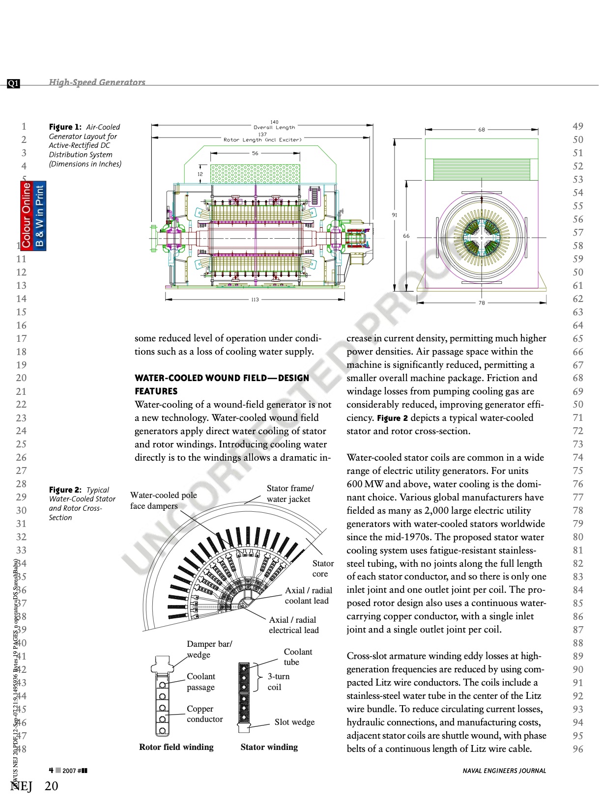
Figure 2: Typical
Water-Cooled Stator
and Rotor Cross-
Section
4 & 2007 #]]
NEJ 20
some reduced level of operation under condi-
tions such as a loss of cooling water supply.
WATER-COOLED WOUND FIELD—DESIGN
FEATURES
Water-cooling of a wound-field generator is not
a new technology. Water-cooled wound field
generators apply direct water cooling of stator
and rotor windings. Introducing cooling water
directly is to the windings allows a dramatic in-
Water-cooled pole
face dampers
Stator frame/
water jacket
Damper bar/
wedge
Coolant
passage
Copper
conductor
Stator
core
Axial / radial
coolant lead
Axial / radial
electrical lead
Coolant
tube
3-turn
coil
Slot wedge
Rotor field winding Stator winding
crease in current density, permitting much higher
power densities. Air passage space within the
machine is significantly reduced, permitting a
smaller overall machine package. Friction and
windage losses from pumping cooling gas are
considerably reduced, improving generator effi-
ciency. Figure 2 depicts a typical water-cooled
stator and rotor cross-section.
Water-cooled stator coils are common in a wide
range of electric utility generators. For units
600 MW and above, water cooling is the domi-
nant choice. Various global manufacturers have
fielded as many as 2,000 large electric utility
generators with water-cooled stators worldwide
since the mid-1970s. The proposed stator water
cooling system uses fatigue-resistant stainless-
steel tubing, with no joints along the full length
of each stator conductor, and so there is only one
inlet joint and one outlet joint per coil. The pro-
posed rotor design also uses a continuous water-
carrying copper conductor, with a single inlet
joint and a single outlet joint per coil.
Cross-slot armature winding eddy losses at high-
generation frequencies are reduced by using com-
pacted Litz wire conductors. The coils include a
stainless-steel water tube in the center of the Litz
wire bundle. To reduce circulating current losses,
hydraulic connections, and manufacturing costs,
adjacent stator coils are shuttle wound, with phase
belts of a continuous length of Litz wire cable.
NAVAL ENGINEERS JOURNAL
49
50
51
52
53
54
55
56
57
58
59
50
61
62
63
64
65
66
67
68
69
50
71
72
73
74
75
76
77
78
79
80
81
82
83
84
85
86
87
88
89
90
91
92
93
94
95
96 |