Search Gas Turbine Power for Data Center Publications search was updated real-time via Filemaker on:
Search Completed | Title | GE Power Heavy-Duty Gas Turbine Operating and Maintenance Considerations GER-362OP
Original File Name Searched: 20210911093317_93385.pdf | Google It | Yahoo | Bing
Page | 009 casings, turbine shell, and internal stationary turbine shrouds
that allow the penetration of an optical borescope into the
compressor or turbine flow path area. Borescope inspection
access locations for the various frame sizes can be found in
Appendix E.
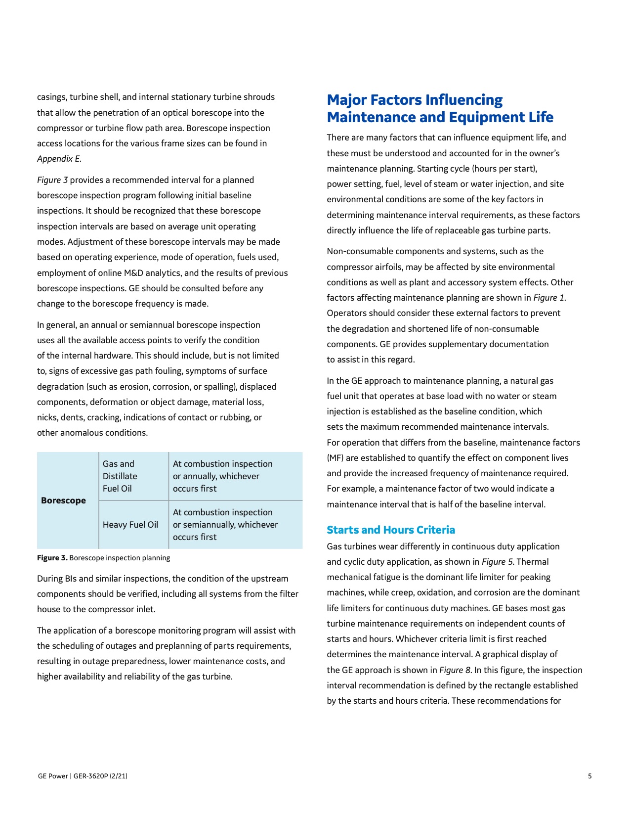
Figure 3 provides a recommended interval for a planned
borescope inspection program following initial baseline
inspections. It should be recognized that these borescope
inspection intervals are based on average unit operating
modes. Adjustment of these borescope intervals may be made
based on operating experience, mode of operation, fuels used,
employment of online M&D analytics, and the results of previous
borescope inspections. GE should be consulted before any
change to the borescope frequency is made.
In general, an annual or semiannual borescope inspection
uses all the available access points to verify the condition
of the internal hardware. This should include, but is not limited
to, signs of excessive gas path fouling, symptoms of surface
degradation (such as erosion, corrosion, or spalling), displaced
components, deformation or object damage, material loss,
nicks, dents, cracking, indications of contact or rubbing, or
other anomalous conditions.
Gas and
Distillate
Fuel Oil
At combustion inspection
or annually, whichever
occurs first
Borescope
Heavy Fuel Oil
At combustion inspection
or semiannually, whichever
occurs first
Figure 3. Borescope inspection planning
During BIs and similar inspections, the condition of the upstream
components should be verified, including all systems from the filter
house to the compressor inlet.
The application of a borescope monitoring program will assist with
the scheduling of outages and preplanning of parts requirements,
resulting in outage preparedness, lower maintenance costs, and
higher availability and reliability of the gas turbine.
Major Factors Influencing
Maintenance and Equipment Life
There are many factors that can influence equipment life, and
these must be understood and accounted for in the owner’s
maintenance planning. Starting cycle (hours per start),
power setting, fuel, level of steam or water injection, and site
environmental conditions are some of the key factors in
determining maintenance interval requirements, as these factors
directly influence the life of replaceable gas turbine parts.
Non-consumable components and systems, such as the
compressor airfoils, may be affected by site environmental
conditions as well as plant and accessory system effects. Other
factors affecting maintenance planning are shown in Figure 1.
Operators should consider these external factors to prevent
the degradation and shortened life of non-consumable
components. GE provides supplementary documentation
to assist in this regard.
In the GE approach to maintenance planning, a natural gas
fuel unit that operates at base load with no water or steam
injection is established as the baseline condition, which
sets the maximum recommended maintenance intervals.
For operation that differs from the baseline, maintenance factors
(MF) are established to quantify the effect on component lives
and provide the increased frequency of maintenance required.
For example, a maintenance factor of two would indicate a
maintenance interval that is half of the baseline interval.
Starts and Hours Criteria
Gas turbines wear differently in continuous duty application
and cyclic duty application, as shown in Figure 5. Thermal
mechanical fatigue is the dominant life limiter for peaking
machines, while creep, oxidation, and corrosion are the dominant
life limiters for continuous duty machines. GE bases most gas
turbine maintenance requirements on independent counts of
starts and hours. Whichever criteria limit is first reached
determines the maintenance interval. A graphical display of
the GE approach is shown in Figure 8. In this figure, the inspection
interval recommendation is defined by the rectangle established
by the starts and hours criteria. These recommendations for
GE Power | GER-3620P (2/21) 5 |