Search Gas Turbine Power for Data Center Publications search was updated real-time via Filemaker on:
Search Completed | Title | Gas Turbine Combined Cycle Power Plants Mitsubishi Heavy Industries
Original File Name Searched: gtcc.pdf | Google It | Yahoo | Bing
Page | 007 F-series
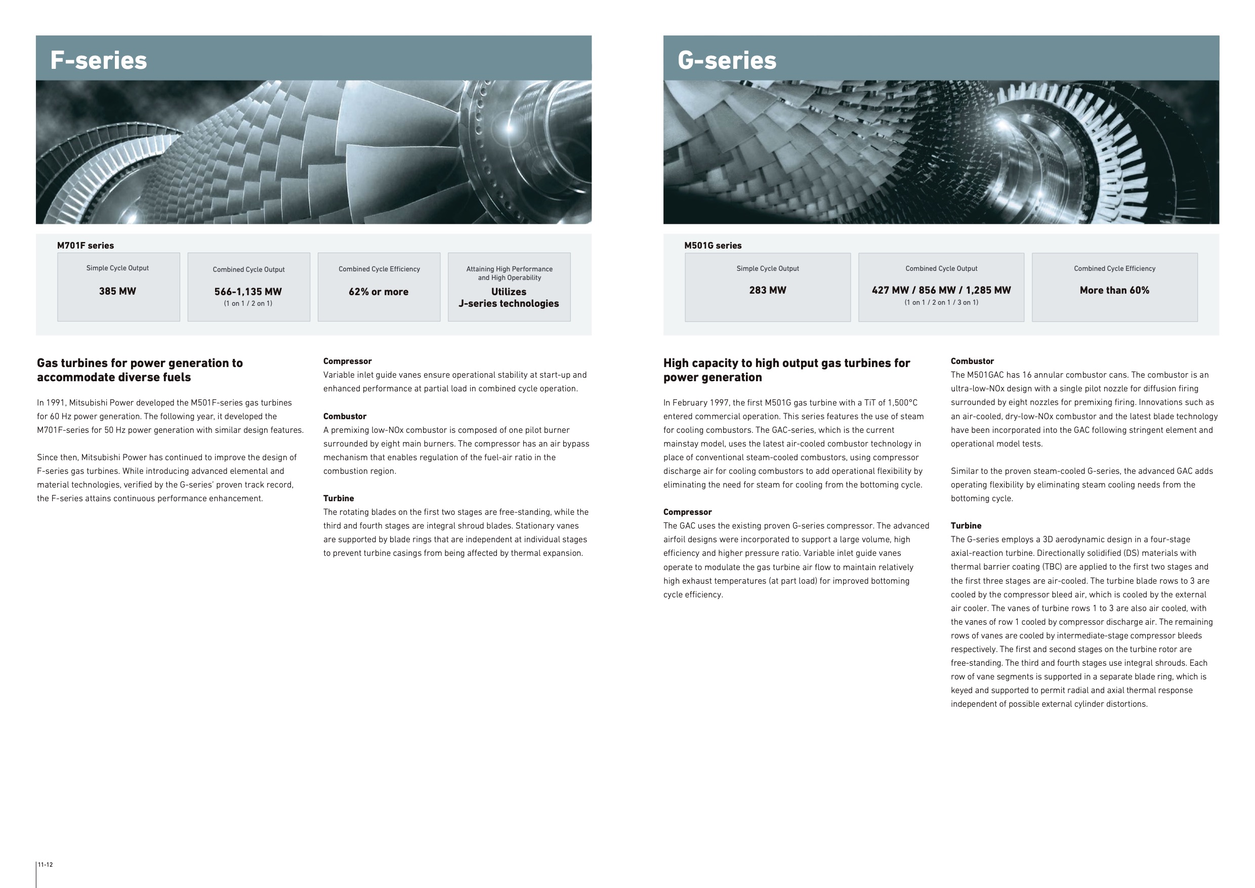
M701F series
Simple Cycle Output
385 MW
Combined Cycle Output
566-1,135 MW
(1 on 1 / 2 on 1)
Gas turbines for power generation to
accommodate diverse fuels
In 1991, Mitsubishi Power developed the M501F-series gas turbines
for 60 Hz power generation. The following year, it developed the
M701F-series for 50 Hz power generation with similar design features.
Since then, Mitsubishi Power has continued to improve the design of
F-series gas turbines. While introducing advanced elemental and
material technologies, verified by the G-series’ proven track record,
the F-series attains continuous performance enhancement.
11-12
Combined Cycle Efficiency
62% or more
Attaining High Performance
and High Operability
Utilizes
J-series technologies
Compressor
Variable inlet guide vanes ensure operational stability at start-up and
enhanced performance at partial load in combined cycle operation.
Combustor
A premixing low-NOx combustor is composed of one pilot burner
surrounded by eight main burners. The compressor has an air bypass
mechanism that enables regulation of the fuel-air ratio in the
combustion region.
Turbine
The rotating blades on the first two stages are free-standing, while the
third and fourth stages are integral shroud blades. Stationary vanes
are supported by blade rings that are independent at individual stages
to prevent turbine casings from being affected by thermal expansion.
G-series
M501G series
Simple Cycle Output
283 MW
Combined Cycle Output
427 MW / 856 MW / 1,285 MW
(1 on 1 / 2 on 1 / 3 on 1)
Combined Cycle Efficiency
More than 60%
High capacity to high output gas turbines for
power generation
In February 1997, the first M501G gas turbine with a TiT of 1,500°C
entered commercial operation. This series features the use of steam
for cooling combustors. The GAC-series, which is the current
mainstay model, uses the latest air-cooled combustor technology in
place of conventional steam-cooled combustors, using compressor
discharge air for cooling combustors to add operational flexibility by
eliminating the need for steam for cooling from the bottoming cycle.
Compressor
The GAC uses the existing proven G-series compressor. The advanced
airfoil designs were incorporated to support a large volume, high
efficiency and higher pressure ratio. Variable inlet guide vanes
operate to modulate the gas turbine air flow to maintain relatively
high exhaust temperatures (at part load) for improved bottoming
cycle efficiency.
Combustor
The M501GAC has 16 annular combustor cans. The combustor is an
ultra-low-NOx design with a single pilot nozzle for diffusion firing
surrounded by eight nozzles for premixing firing. Innovations such as
an air-cooled, dry-low-NOx combustor and the latest blade technology
have been incorporated into the GAC following stringent element and
operational model tests.
Similar to the proven steam-cooled G-series, the advanced GAC adds
operating flexibility by eliminating steam cooling needs from the
bottoming cycle.
Turbine
The G-series employs a 3D aerodynamic design in a four-stage
axial-reaction turbine. Directionally solidified (DS) materials with
thermal barrier coating (TBC) are applied to the first two stages and
the first three stages are air-cooled. The turbine blade rows to 3 are
cooled by the compressor bleed air, which is cooled by the external
air cooler. The vanes of turbine rows 1 to 3 are also air cooled, with
the vanes of row 1 cooled by compressor discharge air. The remaining
rows of vanes are cooled by intermediate-stage compressor bleeds
respectively. The first and second stages on the turbine rotor are
free-standing. The third and fourth stages use integral shrouds. Each
row of vane segments is supported in a separate blade ring, which is
keyed and supported to permit radial and axial thermal response
independent of possible external cylinder distortions. |