Search Gas Turbine Power for Data Center Publications search was updated real-time via Filemaker on:
Page | 001 4.2.1
Cooling Design Analysis
4.2.1-1 Introduction
The technology of cooling gas turbine components via internal convective fl ows
of single-phase gases has developed over the years from simple smooth cooling
passages to very complex geometries involving many differing surfaces, architectures,
and fl uid-surface interactions. The fundamental aim of this technology area is to
obtain the highest overall cooling effectiveness with the lowest possible penalty on
the thermodynamic cycle performance. As a thermodynamic Brayton cycle, the
effi ciency of the gas turbine engine can be raised substantially by increasing the fi ring
temperature of the turbine. Modern gas turbine systems are fi red at temperatures in
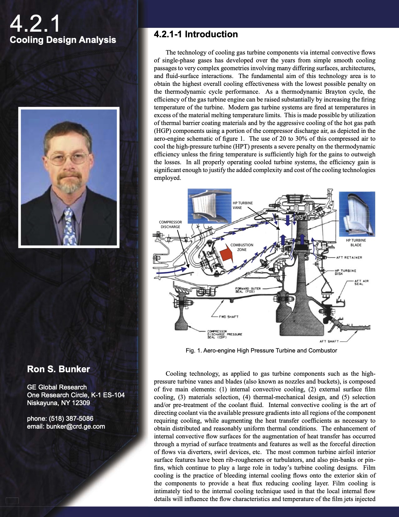
excess of the material melting temperature limits. This is made possible by utilization
of thermal barrier coating materials and by the aggressive cooling of the hot gas path
(HGP) components using a portion of the compressor discharge air, as depicted in the
aero-engine schematic of fi gure 1. The use of 20 to 30% of this compressed air to
cool the high-pressure turbine (HPT) presents a severe penalty on the thermodynamic
effi ciency unless the fi ring temperature is suffi ciently high for the gains to outweigh
the losses. In all properly operating cooled turbine systems, the effi ciency gain is
signifi cant enough to justify the added complexity and cost of the cooling technologies
employed.
HP TURBINE
HP TURBINE
VANE
VANE
COMPRESSOR
COMPRESSOR
DISCHARGE
DISCHARGE
HP TURBINE
HP TURBINE
BLADE
BLADE
COMBUSTION
COMBUSTION
ZONE
ZONE
Fig. 1. Aero-engine High Pressure Turbine and Combustor
Ron S. Bunker
GE Global Research
One Research Circle, K-1 ES-104
Niskayuna, NY 12309
phone: (518) 387-5086
email: bunker@crd.ge.com
295 295
Cooling technology, as applied to gas turbine components such as the high-
pressure turbine vanes and blades (also known as nozzles and buckets), is composed
of fi ve main elements: (1) internal convective cooling, (2) external surface fi lm
cooling, (3) materials selection, (4) thermal-mechanical design, and (5) selection
and/or pre-treatment of the coolant fl uid. Internal convective cooling is the art of
directing coolant via the available pressure gradients into all regions of the component
requiring cooling, while augmenting the heat transfer coeffi cients as necessary to
obtain distributed and reasonably uniform thermal conditions. The enhancement of
internal convective fl ow surfaces for the augmentation of heat transfer has occurred
through a myriad of surface treatments and features as well as the forceful direction
of fl ows via diverters, swirl devices, etc. The most common turbine airfoil interior
surface features have been rib-rougheners or turbulators, and also pin-banks or pin-
fi ns, which continue to play a large role in today’s turbine cooling designs. Film
cooling is the practice of bleeding internal cooling fl ows onto the exterior skin of
the components to provide a heat fl ux reducing cooling layer. Film cooling is
intimately tied to the internal cooling technique used in that the local internal fl ow
details will infl uence the fl ow characteristics and temperature of the fi lm jets injected |