Search Gas Turbine Power for Data Center Publications search was updated real-time via Filemaker on:
Search Completed | Title | Applying Natural Gas Engine Generators to Hyperscale Data Centers
Original File Name Searched: WP286V1.pdf | Google It | Yahoo | Bing
Page | 014 Schneider Electric – Data Center Science Center White Paper 286 Version 1 14
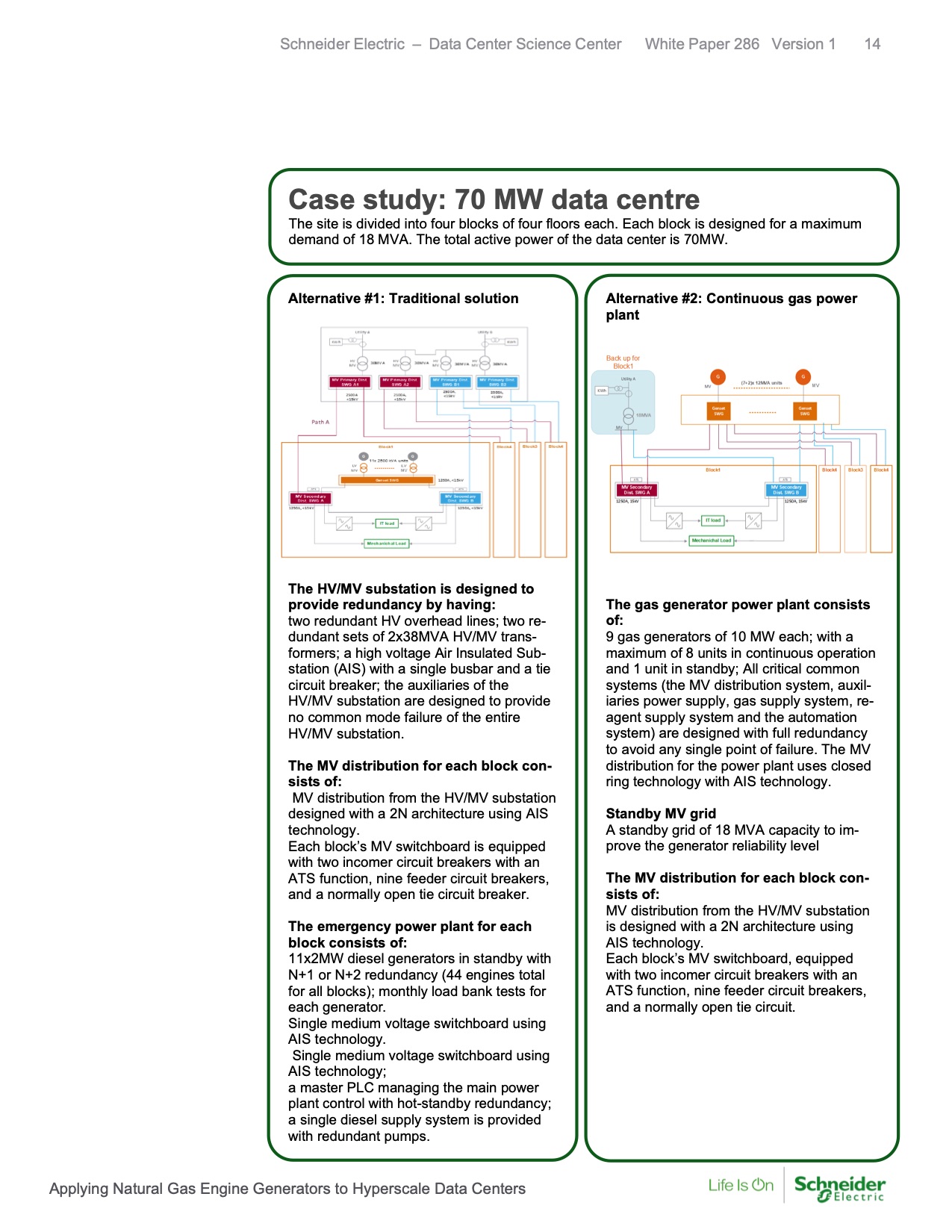
Case study: 70 MW data centre
The site is divided into four blocks of four floors each. Each block is designed for a maximum
demand of 18 MVA. The total active power of the data center is 70MW.
Alternative #1: Traditional solution
Alternative #2: Continuous gas power
plant
The HV/MV substation is designed to
provide redundancy by having:
two redundant HV overhead lines; two re-
dundant sets of 2x38MVA HV/MV trans-
formers; a high voltage Air Insulated Sub-
station (AIS) with a single busbar and a tie
circuit breaker; the auxiliaries of the
HV/MV substation are designed to provide
no common mode failure of the entire
HV/MV substation.
The MV distribution for each block con-
sists of:
MV distribution from the HV/MV substation
designed with a 2N architecture using AIS
technology.
Each block’s MV switchboard is equipped
with two incomer circuit breakers with an
ATS function, nine feeder circuit breakers,
and a normally open tie circuit breaker.
The emergency power plant for each
block consists of:
11x2MW diesel generators in standby with
N+1 or N+2 redundancy (44 engines total
for all blocks); monthly load bank tests for
each generator.
Single medium voltage switchboard using
AIS technology.
Single medium voltage switchboard using
AIS technology;
a master PLC managing the main power
plant control with hot-standby redundancy;
a single diesel supply system is provided
with redundant pumps.
The gas generator power plant consists
of:
9 gas generators of 10 MW each; with a
maximum of 8 units in continuous operation
and 1 unit in standby; All critical common
systems (the MV distribution system, auxil-
iaries power supply, gas supply system, re-
agent supply system and the automation
system) are designed with full redundancy
to avoid any single point of failure. The MV
distribution for the power plant uses closed
ring technology with AIS technology.
Standby MV grid
A standby grid of 18 MVA capacity to im-
prove the generator reliability level
The MV distribution for each block con-
sists of:
MV distribution from the HV/MV substation
is designed with a 2N architecture using
AIS technology.
Each block’s MV switchboard, equipped
with two incomer circuit breakers with an
ATS function, nine feeder circuit breakers,
and a normally open tie circuit.
equipped with two incomer circuit breakers
with an ATS function, nine feeder circuit
breakers, and a normally open tie circuit
breaker.
Applying Natural Gas Engine Generators to Hyperscale Data Centers |