Search Gas Turbine Power for Data Center Publications search was updated real-time via Filemaker on:
Search Completed | Title | Applying Natural Gas Engine Generators to Hyperscale Data Centers
Original File Name Searched: WP286V1.pdf | Google It | Yahoo | Bing
Page | 012 Figure 11
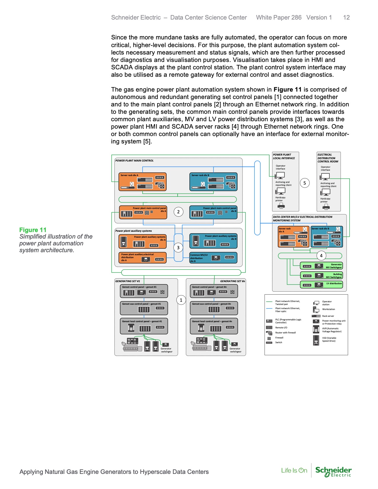
Simplified illustration of the
power plant automation
system architecture.
Schneider Electric – Data Center Science Center White Paper 286 Version 1 12
Since the more mundane tasks are fully automated, the operator can focus on more
critical, higher-level decisions. For this purpose, the plant automation system col-
lects necessary measurement and status signals, which are then further processed
for diagnostics and visualisation purposes. Visualisation takes place in HMI and
SCADA displays at the plant control station. The plant control system interface may
also be utilised as a remote gateway for external control and asset diagnostics.
The gas engine power plant automation system shown in Figure 11 is comprised of
autonomous and redundant generating set control panels [1] connected together
and to the main plant control panels [2] through an Ethernet network ring. In addition
to the generating sets, the common main control panels provide interfaces towards
common plant auxiliaries, MV and LV power distribution systems [3], as well as the
power plant HMI and SCADA server racks [4] through Ethernet network rings. One
or both common control panels can optionally have an interface for external monitor-
ing system [5].
POWER PLANT
LOCAL INTERFACE
POWER PLANT MAIN CONTROL
ELECTRICAL
DISTRIBUTION
CONTROL ROOM
Operator
interface
Operator
interface
Server rack div A Server rack div B
Archiving and
reporting client
5
Archiving and
reporting client
Hardcopy
printer
Hardcopy
printer
Power plant main control panel
div A
2
DATA CENTER MV/LV ELECTRICAL DISTRIBUTION
MONITORING SYSTEM
Power plant auxiliary systems
Server rack
div A
Server rack div B
Power plant auxiliary systems
div A
3
Power plant auxiliary electrical
distribution
div A
4
GENERATING SET #1
Genset control panel – genset #1 1
Genset aux control panel – genset #1 Genset local control panel – genset #1
WÄRTSILÄ
UNIC
Power plant main control panel
div B
Power plant auxiliary systems
div B
Common MV/LV
distribution
div B
GENERATING SET #n
Genset control panel – genset #n
Genset aux control panel – genset #n
Genset local control panel – genset #n
WÄRTSILÄ
UNIC
Generator
MV Switchgear
Building
MV Switchgear
LV distribution
Plant network Ethernet,
Twisted pair
Plant network Ethernet,
Fiber optic
PLC (Programmable Logic
Controller)
Remote I/O
Router with firewall
Firewall
Switch
Operator
station
Workstation
Rack server
Power monitoring unit
or Protection relay
AVR (Automatic
Voltage Regulator)
VSD (Variable
Speed Drive)
Generator
switchgear
Generator
switchgear
Applying Natural Gas Engine Generators to Hyperscale Data Centers |