Search Gas Turbine Power for Data Center Publications search was updated real-time via Filemaker on:
Search Completed | Title | Applying Natural Gas Engine Generators to Hyperscale Data Centers
Original File Name Searched: WP286V1.pdf | Google It | Yahoo | Bing
Page | 010 Schneider Electric – Data Center Science Center White Paper 286 Version 1 10
could enhance the reliability and decrease the probability of having a failure in oper-
ation.
Gas generator 1
10MW unit
15 kV
Gen1 SWB
15 kV, Icu 31,5kA
Incomer 1250 A
Ring feeder 2500 A
Load feeder 1250 A
Generator power plant – 9 units (7+2 redundancy)
Gas generator 3
10MW unit
Gas generator 4
10MW unit
Gas generator 5
10MW unit
Gas generator 6
10MW unit
Gas generator 7
10MW unit
Gas generator 8
10MW unit
15 kV
15 kV
15 kV
15 kV
15 kV
15 kV
Gen3 SWB
15 kV, Icu 31,5kA
Incomer 1250 A
Ring feeder 2500 A
Load feeder 1250 A
Gen4 SWB
15 kV, Icu 31,5kA
Incomer 1250 A
Ring feeder 2500 A
Load feeder 1250 A
Gen5 SWB
15 kV, Icu 31,5kA
Incomer 1250 A
Ring feeder 2500 A
Load feeder 1250 A
Gen6 SWB
15 kV, Icu 31,5kA
Incomer 1250 A
Ring feeder 2500 A
Load feeder 1250 A
Gen7 SWB
15 kV, Icu 31,5kA
Incomer 1250 A
Ring feeder 2500 A
Load feeder 1250 A
Gen8 SWB
15 kV, Icu 31,5kA
Incomer 1250 A
Ring feeder 2500 A
Load feeder 1250 A
Gas generator 2
10MW unit
15 kV
Gen2 SWB
15 kV, Icu 31,5kA
Incomer 1250 A
Ring feeder 2500 A
Load feeder 1250 A
Gas generator 9
10MW unit
15 kV
Gen9 SWB
15 kV, Icu 31,5kA
Incomer 1250 A
Ring feeder 2500 A
Load feeder 1250 A
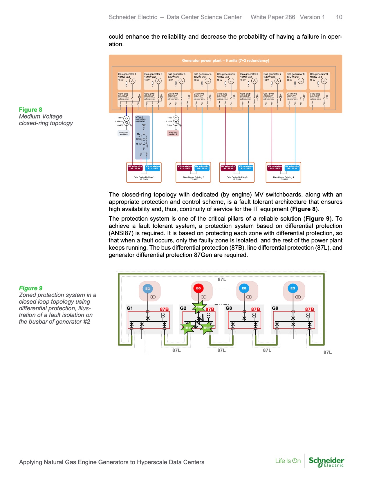
Figure 8
Medium Voltage
closed-ring topology
15kV
1.5 MVA
MV grid
connection
substation
15kV
1.5 MVA
0.4kV
0.4kV
Power plant
auxiliary A
MV
18
MVA
Power plant
auxiliary B
15 kV
MV substation
A1 - 15 kV
MV substation
B1 - 15 kV
MV substation
A2 - 15 kV
MV substation
B2 - 15 kV
MV substation
A3 - 15 kV
MV substation
B3 - 15 kV
MV substation
A4 - 15 kV
MV substation
B4 - 15 kV
Data Center Building 1
17.5 MW
Data Center Building 2
17.5 MW
Data Center Building 3
17.5 MW
Data Center Building 4
17.5 MW
The closed-ring topology with dedicated (by engine) MV switchboards, along with an
appropriate protection and control scheme, is a fault tolerant architecture that ensures
high availability and, thus, continuity of service for the IT equipment (Figure 8).
The protection system is one of the critical pillars of a reliable solution (Figure 9). To
achieve a fault tolerant system, a protection system based on differential protection
(ANSI87) is required. It is based on protecting each zone with differential protection, so
that when a fault occurs, only the faulty zone is isolated, and the rest of the power plant
keeps running. The bus differential protection (87B), line differential protection (87L), and
generator differential protection 87Gen are required.
87L
EG
EG EG EG
Figure 9
Zoned protection system in a
closed loop topology using
differential protection, illus-
tration of a fault isolation on
the busbar of generator #2
G1
TRIP
87B G2 87B G8 87B
G9 87B
TRIP
TRIP
87L 87L 87L
87L
Applying Natural Gas Engine Generators to Hyperscale Data Centers |