Search Gas Turbine Power for Data Center Publications search was updated real-time via Filemaker on:
Search Completed | Title | Applying Natural Gas Engine Generators to Hyperscale Data Centers
Original File Name Searched: WP286V1.pdf | Google It | Yahoo | Bing
Page | 009 Schneider Electric – Data Center Science Center White Paper 286 Version 1 9
backup grid connection, in order to have a cost competitive solution proved to be the
best choice.
Table 2
Availability (%) and Mean Time
Between Failure (per year)
comparison. Assumptions: only
the generator units are consid-
ered, the power plant auxiliary
systems and electrical distribu-
tion equipment are not in-
cluded)
# of Generators Availability MTBF (years)
7+2 generators 99.99173% 10
7+3 generators 99.99992% 557
7+2 generator and
99.99999% 3,060
18 MVA grid back-up
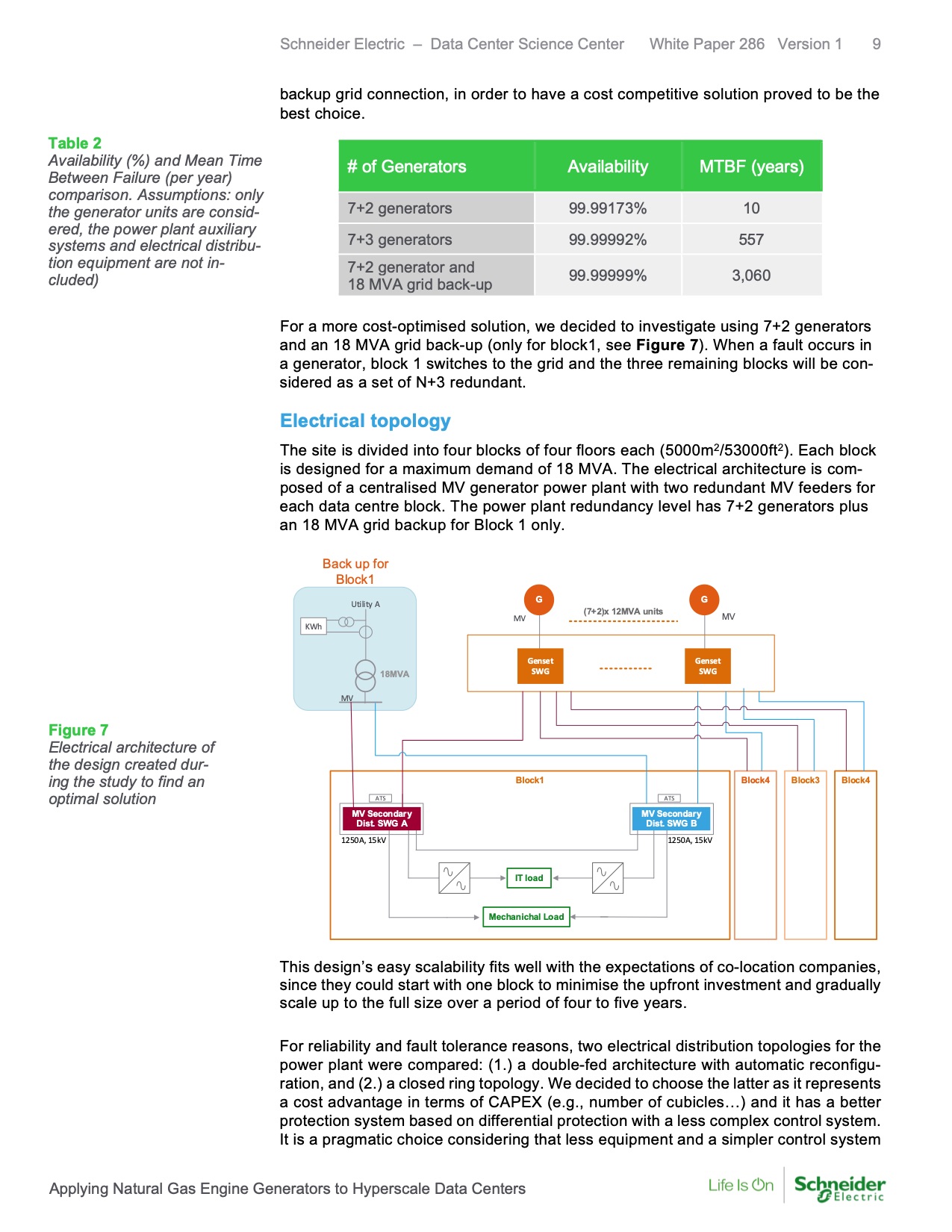
For a more cost-optimised solution, we decided to investigate using 7+2 generators
and an 18 MVA grid back-up (only for block1, see Figure 7). When a fault occurs in
a generator, block 1 switches to the grid and the three remaining blocks will be con-
sidered as a set of N+3 redundant.
Electrical topology
The site is divided into four blocks of four floors each (5000m2/53000ft2). Each block
is designed for a maximum demand of 18 MVA. The electrical architecture is com-
posed of a centralised MV generator power plant with two redundant MV feeders for
each data centre block. The power plant redundancy level has 7+2 generators plus
an 18 MVA grid backup for Block 1 only.
Back up for
Block1
G
G
Utility A
(7+2)x 12MVA units
MV MV
KWh
18MVA
Genset
SWG
Genset
SWG
MV
Figure 7
Electrical architecture of
the design created dur-
ing the study to find an
optimal solution
Block1
Block4 Block3 Block4
ATS
ATS
MV Secondary
Dist. SWG A
MV Secondary
Dist. SWG B
1250A, 15kV 1250A, 15kV
IT load
Mechanichal Load
This design’s easy scalability fits well with the expectations of co-location companies,
since they could start with one block to minimise the upfront investment and gradually
scale up to the full size over a period of four to five years.
For reliability and fault tolerance reasons, two electrical distribution topologies for the
power plant were compared: (1.) a double-fed architecture with automatic reconfigu-
ration, and (2.) a closed ring topology. We decided to choose the latter as it represents
a cost advantage in terms of CAPEX (e.g., number of cubicles…) and it has a better
protection system based on differential protection with a less complex control system.
It is a pragmatic choice considering that less equipment and a simpler control system
Applying Natural Gas Engine Generators to Hyperscale Data Centers |