Search Gas Turbine Power for Data Center Publications search was updated real-time via Filemaker on:
Search Completed | Title | Applying Natural Gas Engine Generators to Hyperscale Data Centers
Original File Name Searched: WP286V1.pdf | Google It | Yahoo | Bing
Page | 008 Schneider Electric – Data Center Science Center White Paper 286 Version 1 8
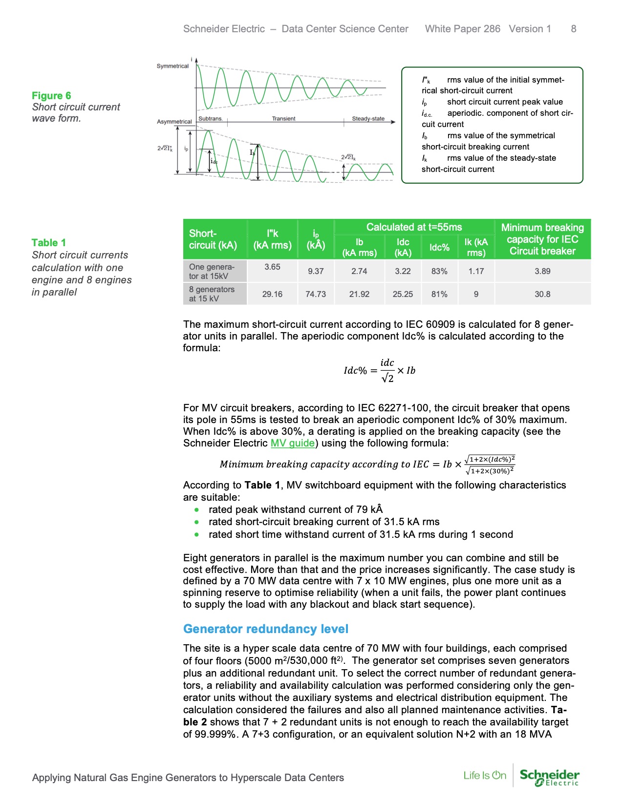
Figure 6
Short circuit current
wave form.
Ib
idc
I"
k rms value of the initial symmet-
rical short-circuit current
ip short circuit current peak value
id.c. aperiodic. component of short cir-
cuit current
Ib rms value of the symmetrical
short-circuit breaking current
Ik rms value of the steady-state
short-circuit current
Calculated at t=55ms Minimum breaking
Short-
I"k
ip
Table 1
Short circuit currents
calculation with one
engine and 8 engines
in parallel
circuit (kA)
(kA rms)
(kÂ)
Ib
(kA rms)
Idc
(kA) Idc% Ik (kA
rms)
capacity for IEC
Circuit breaker
One genera-
tor at 15kV
3.65 9.37 2.74 3.22 83% 1.17 3.89
8 generators
at 15 kV 29.16 74.73 21.92 25.25 81% 9 30.8
The maximum short-circuit current according to IEC 60909 is calculated for 8 gener-
ator units in parallel. The aperiodic component Idc% is calculated according to the
formula:
𝐼𝐼𝐼𝐼𝐼𝐼% =
𝑖𝑖𝐼𝐼𝐼𝐼
√2
× 𝐼𝐼𝐼𝐼
For MV circuit breakers, according to IEC 62271-100, the circuit breaker that opens
its pole in 55ms is tested to break an aperiodic component Idc% of 30% maximum.
When Idc% is above 30%, a derating is applied on the breaking capacity (see the
Schneider Electric MV guide) using the following formula:
𝑀𝑀𝑖𝑖𝑀𝑀𝑖𝑖𝑀𝑀𝑀𝑀𝑀𝑀 𝐼𝐼𝑏𝑏𝑏𝑏𝑏𝑏𝑏𝑏𝑖𝑖𝑀𝑀𝑏𝑏 𝐼𝐼𝑏𝑏𝑐𝑐𝑏𝑏𝐼𝐼𝑖𝑖𝑐𝑐𝑐𝑐 𝑏𝑏𝐼𝐼𝐼𝐼𝑎𝑎𝑏𝑏𝐼𝐼𝑖𝑖𝑀𝑀𝑏𝑏 𝑐𝑐𝑎𝑎 𝐼𝐼𝐼𝐼𝐼𝐼= 𝐼𝐼𝐼𝐼 × �1+2×(𝐼𝐼𝐼𝐼𝐼𝐼%)2
�1+2×(30%)2
According to Table 1, MV switchboard equipment with the following characteristics
are suitable:
• rated peak withstand current of 79 kÂ
• rated short-circuit breaking current of 31.5 kA rms
• rated short time withstand current of 31.5 kA rms during 1 second
Eight generators in parallel is the maximum number you can combine and still be
cost effective. More than that and the price increases significantly. The case study is
defined by a 70 MW data centre with 7 x 10 MW engines, plus one more unit as a
spinning reserve to optimise reliability (when a unit fails, the power plant continues
to supply the load with any blackout and black start sequence).
Generator redundancy level
The site is a hyper scale data centre of 70 MW with four buildings, each comprised
of four floors (5000 m2/530,000 ft2). The generator set comprises seven generators
plus an additional redundant unit. To select the correct number of redundant genera-
tors, a reliability and availability calculation was performed considering only the gen-
erator units without the auxiliary systems and electrical distribution equipment. The
calculation considered the failures and also all planned maintenance activities. Ta-
ble 2 shows that 7 + 2 redundant units is not enough to reach the availability target
of 99.999%. A 7+3 configuration, or an equivalent solution N+2 with an 18 MVA
Applying Natural Gas Engine Generators to Hyperscale Data Centers |