Search Gas Turbine Power for Data Center Publications search was updated real-time via Filemaker on:
Page | 001 4.2.2.1
Airfoil Film Cooling
4.2.2.1-1 Introduction
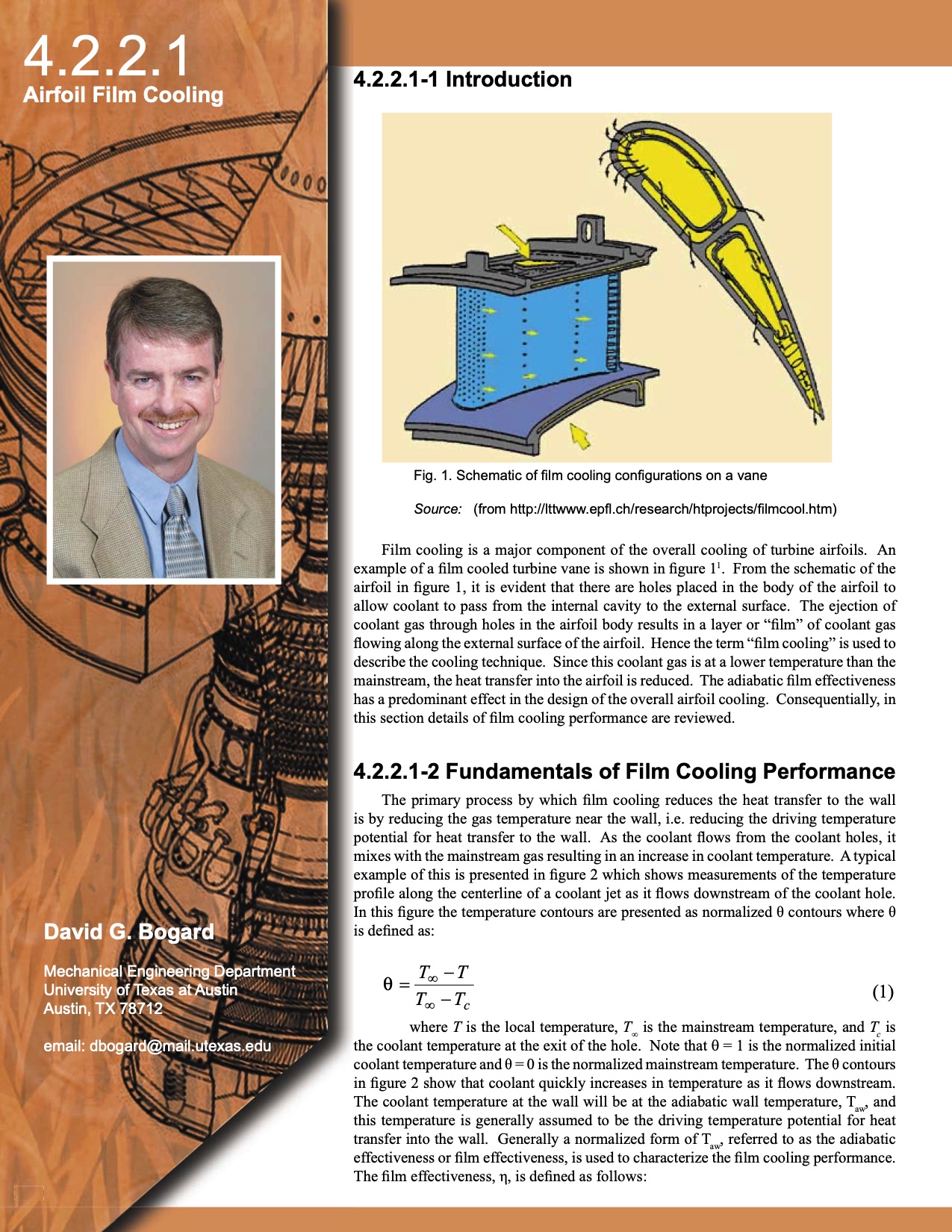
Fig. 1. Schematic of fi lm cooling confi gurations on a vane
Source: (from http://lttwww.epfl .ch/research/htprojects/fi lmcool.htm)
Film cooling is a major component of the overall cooling of turbine airfoils. An
example of a fi lm cooled turbine vane is shown in fi gure 11. From the schematic of the
airfoil in fi gure 1, it is evident that there are holes placed in the body of the airfoil to
allow coolant to pass from the internal cavity to the external surface. The ejection of
coolant gas through holes in the airfoil body results in a layer or “fi lm” of coolant gas
fl owing along the external surface of the airfoil. Hence the term “fi lm cooling” is used to
describe the cooling technique. Since this coolant gas is at a lower temperature than the
mainstream, the heat transfer into the airfoil is reduced. The adiabatic fi lm effectiveness
has a predominant effect in the design of the overall airfoil cooling. Consequentially, in
this section details of fi lm cooling performance are reviewed.
4.2.2.1-2 Fundamentals of Film Cooling Performance
The primary process by which fi lm cooling reduces the heat transfer to the wall
is by reducing the gas temperature near the wall, i.e. reducing the driving temperature
potential for heat transfer to the wall. As the coolant fl ows from the coolant holes, it
mixes with the mainstream gas resulting in an increase in coolant temperature. A typical
example of this is presented in fi gure 2 which shows measurements of the temperature
profi le along the centerline of a coolant jet as it fl ows downstream of the coolant hole.
In this fi gure the temperature contours are presented as normalized θ contours where θ
is defi ned as:
David G. Bogard
Mechanical Engineering Department
University of Texas at Austin
Austin, TX 78712
email: dbogard@mail.utexas.edu
T
−
T
∝
=
θ (1)
T
−
∝
c T
where T is the local temperature, T
∝ is the mainstream temperature, and T
is
c
the coolant temperature at the exit of the hole. Note that θ = 1 is the normalized initial
coolant temperature and θ = 0 is the normalized mainstream temperature. The θ contours
in fi gure 2 show that coolant quickly increases in temperature as it fl ows downstream.
The coolant temperature at the wall will be at the adiabatic wall temperature, Taw, and
this temperature is generally assumed to be the driving temperature potential for heat
transfer into the wall. Generally a normalized form of Taw, referred to as the adiabatic
effectiveness or fi lm effectiveness, is used to characterize the fi lm cooling performance.
The fi lm effectiveness, η, is defi ned as follows:
309 309 |