Search Gas Turbine Power for Data Center Publications search was updated real-time via Filemaker on:
Page | 001 4.2.3
Airfoil Endwall Heat Transfer
4.2.3-1 Introduction
The fl ow in a gas turbine infl uenced by the inner hub and outer casings of the
airfoils is defi ned as secondary or endwall fl ows. These fl ows often contain vortices
that give rise to velocity components that are orthogonal to the primary fl ow direction
as depicted in fi gure 1 by the ribbon arrows, which is specifi c to vane endwalls. These
fl ows constitute one of the most commonplace and widespread three-dimensional
fl ows arising in axial fl ow turbomachinery. In typical modern day turbine designs,
endwall fl ows for fi rst stage vanes are responsible for over 30% of the total pressure
loss through a turbine stage leading to a reduction in turbine effi ciencies on the order
of 3%. While overall airfoil losses have been reduced through the use of three-
dimensional geometries that make use of bowed or leaned airfoils, for example, the
endwalls have remained fairly conventional and the source of much of the remaining
pressure losses. The heat transfer consequences are immense because of the increased
convective coeffi cients and mixing out of fi lm-coolant near the surface. It is clear
from a thermodynamic analysis of a turbine engine, that to improve performance,
there is a need to increase the aspect ratio for turbine airfoils and to increase turbine
inlet temperatures. To improve a turbine’s performance, these trends require that
endwall fl ows be carefully considered in turbine designs.
The endwall fl ow through an airfoil cascade under isothermal conditions
with an approaching two-dimensional boundary layer agrees well with that depicted
in fi gure 1. The fl ow model shows that the inlet boundary layer separates from
the approaching endwall to form what is known as a horseshoe vortex. One leg of
the horseshoe vortex, present on the pressure side of the airfoil (concave side), is
convected into the passage and is promoted by the inherent pressure gradient between
the two airfoil surfaces. This pressure side leg of the horseshoe vortex develops into
what is known as the passage vortex. The other leg of the horseshoe vortex, present
on the suction side of the airfoil (convex side), has an opposite sense of rotation to
the larger passage vortex and develops into what is known as a counter vortex. The
counter vortex can be thought of as a planet rotating about the axis of the passage
vortex (sun). The actual rotation of the vortices depicted in fi gure 1 were drawn
to exaggerate the vortex motion and for the passage vortex is generally about two
rotations before exiting the airfoil passage. While this picture represents a time-
averaged representation, measured data indicates that the vortex is not steady. While
the development of the vortical structures originates in the endwall regions, the growth
can be such that the passage vortex occupies a large portion of the airfoil exit. This
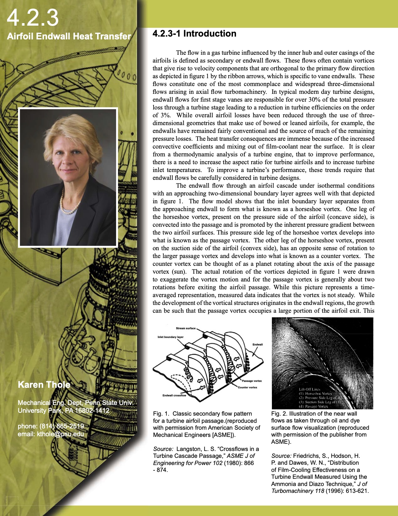
Karen Thole
Mechanical Eng. Dept, Penn State Univ.
University Park, PA 16802-1412
phone: (814) 865-2519
email: kthole@psu.edu
Fig. 1. Classic secondary fl ow pattern
for a turbine airfoil passage.(reproduced
with permission from American Society of
Mechanical Engineers [ASME]).
Source: Langston, L. S. “Crossfl ows in a
Turbine Cascade Passage,” ASME J of
Engineering for Power 102 (1980): 866
- 874.
Fig. 2. Illustration of the near wall
fl ows as taken through oil and dye
surface fl ow visualization (reproduced
with permission of the publisher from
ASME).
Source: Friedrichs, S., Hodson, H.
P. and Dawes, W. N., “Distribution
of Film-Cooling Effectiveness on a
Turbine Endwall Measured Using the
Ammonia and Diazo Technique,” J of
Turbomachinery 118 (1996): 613-621.
353
353 |