Search Gas Turbine Power for Data Center Publications search was updated real-time via Filemaker on:
Page | 008 7EA USERS GROUP
Inspection
A goal of every engine inspection is not
to miss something that could contrib-
ute to a forced outage. Success requires
qualified technicians equipped with
the most sophisticated tools available
and well connected to company experts
with deep and applicable experience
ready to help diagnose findings that
may be unfamiliar to those at the
plant site.
Mike Hoogsteden, director of field
services, Advanced Turbine Support
LLC, which inspects scores of GE
E-class gas turbines annually, tradi-
tionally opens the 7EA Users Group
meeting with the highly informative
presentation, “What We Are Seeing
in the 7EA Fleet during Our Inspec-
tions.” This is of particular value to
first-timers requiring an engine ori-
entation lesson as well as a primer
on what to look for and where during
inspections to assure reliable service
from the generating asset. The photos
Hoogsteden presents are invaluable.
Pat Myers, the de facto leader of
the 7EA Users Group steering com-
mittee before his retirement as plant
manager of AEP’s Ceredo Generating
Station a couple of years ago, repre-
sented CCJ at the 2017 meeting and
sat in on Hoogsteden’s presentation.
Now a consultant, Myers shares with
clients his extensive knowledge on
plant construction, maintenance, and
operation gained over four decades in
management positions at both gas and
electric companies.
Hoogsteden opened his presenta-
tion by suggesting that owner/opera-
tors review Technical Information
Letters (TILs) issued by the OEM for
their engines, take notes, and bring
their questions to the next user-group
meeting. Colleagues and participating
equipment/services providers, he said,
are the best source of advice on what’s
important and what’s not.
The five TILs at the top of Hoog-
steden’s list for 7EA users are the
following:
n 1884, “7EA R1/S1 Inspection Rec-
ommendations,” which addresses
the need to inspect R1 and S1 air-
foils for possible damage caused by
clashing—the unwanted contact
between the leading edges of S1
stator-vane tips and the trailing
edges of rotor blades in the platform
area.
n 1980, “7EA S1 Suction Side Inspec-
tion Recommendations,” which
advises users to inspect for crack
indications on S1 vanes made of
Type-403 stainless-steel, regardless
of whether clashing damage is in
evidence on S1 and R1 airfoils.
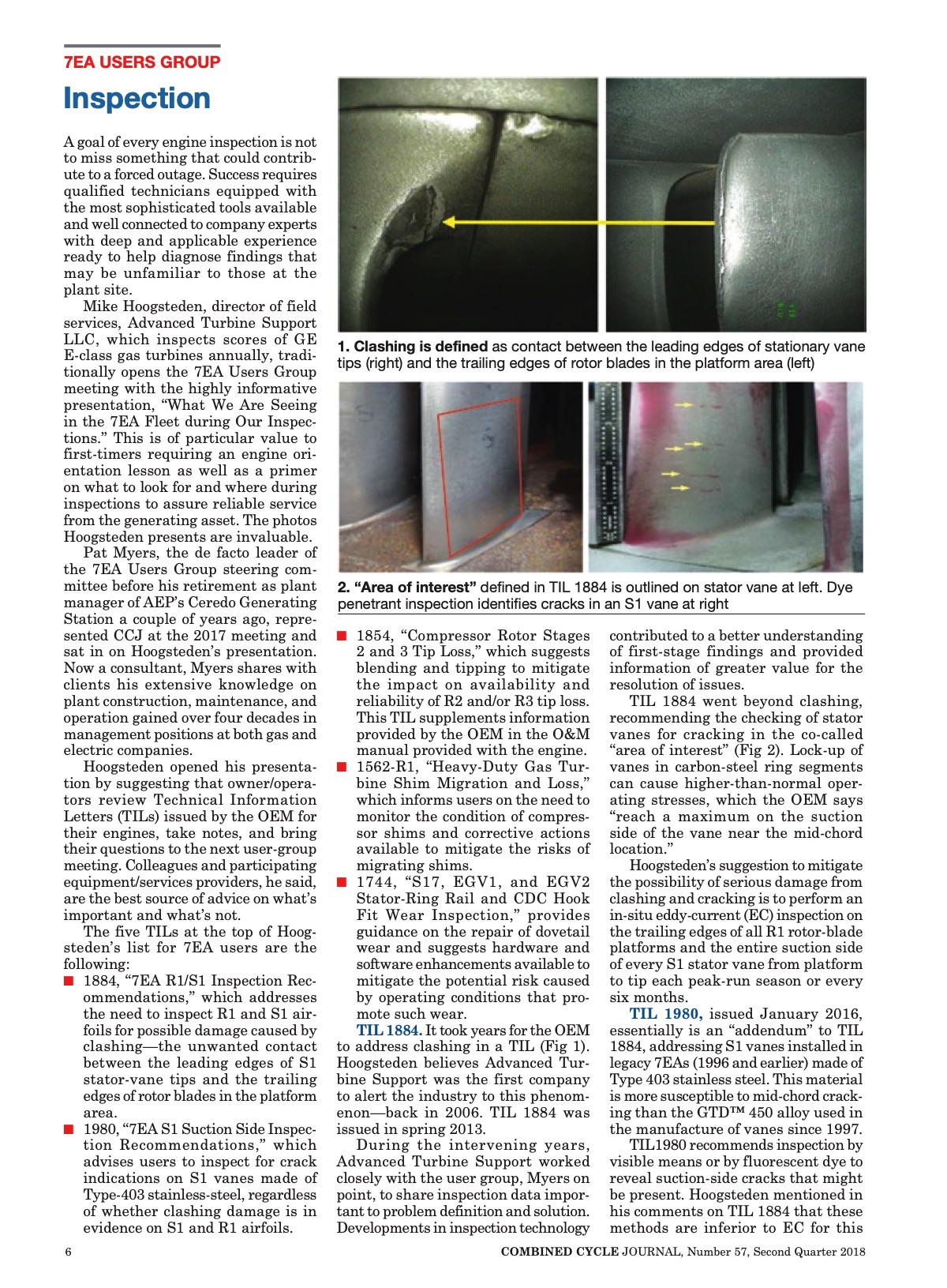
1. Clashing is defined as contact between the leading edges of stationary vane
tips (right) and the trailing edges of rotor blades in the platform area (left)
2. “Area of interest” defined in TIL 1884 is outlined on stator vane at left. Dye
penetrant inspection identifies cracks in an S1 vane at right
n 1854, “Compressor Rotor Stages
2 and 3 Tip Loss,” which suggests
blending and tipping to mitigate
the impact on availability and
reliability of R2 and/or R3 tip loss.
This TIL supplements information
provided by the OEM in the O&M
manual provided with the engine.
n 1562-R1, “Heavy-Duty Gas Tur-
bine Shim Migration and Loss,”
which informs users on the need to
monitor the condition of compres-
sor shims and corrective actions
available to mitigate the risks of
migrating shims.
n 1744, “S17, EGV1, and EGV2
Stator-Ring Rail and CDC Hook
Fit Wear Inspection,” provides
guidance on the repair of dovetail
wear and suggests hardware and
software enhancements available to
mitigate the potential risk caused
by operating conditions that pro-
mote such wear.
TIL 1884. It took years for the OEM
to address clashing in a TIL (Fig 1).
Hoogsteden believes Advanced Tur-
bine Support was the first company
to alert the industry to this phenom-
enon—back in 2006. TIL 1884 was
issued in spring 2013.
During the intervening years,
Advanced Turbine Support worked
closely with the user group, Myers on
point, to share inspection data impor-
tant to problem definition and solution.
Developments in inspection technology
contributed to a better understanding
of first-stage findings and provided
information of greater value for the
resolution of issues.
TIL 1884 went beyond clashing,
recommending the checking of stator
vanes for cracking in the co-called
“area of interest” (Fig 2). Lock-up of
vanes in carbon-steel ring segments
can cause higher-than-normal oper-
ating stresses, which the OEM says
“reach a maximum on the suction
side of the vane near the mid-chord
location.”
Hoogsteden’s suggestion to mitigate
the possibility of serious damage from
clashing and cracking is to perform an
in-situ eddy-current (EC) inspection on
the trailing edges of all R1 rotor-blade
platforms and the entire suction side
of every S1 stator vane from platform
to tip each peak-run season or every
six months.
TIL 1980, issued January 2016,
essentially is an “addendum” to TIL
1884, addressing S1 vanes installed in
legacy 7EAs (1996 and earlier) made of
Type 403 stainless steel. This material
is more susceptible to mid-chord crack-
ing than the GTD™ 450 alloy used in
the manufacture of vanes since 1997.
TIL1980 recommends inspection by
visible means or by fluorescent dye to
reveal suction-side cracks that might
be present. Hoogsteden mentioned in
his comments on TIL 1884 that these
methods are inferior to EC for this
6 COMBINED CYCLE JOURNAL, Number 57, Second Quarter 2018 |